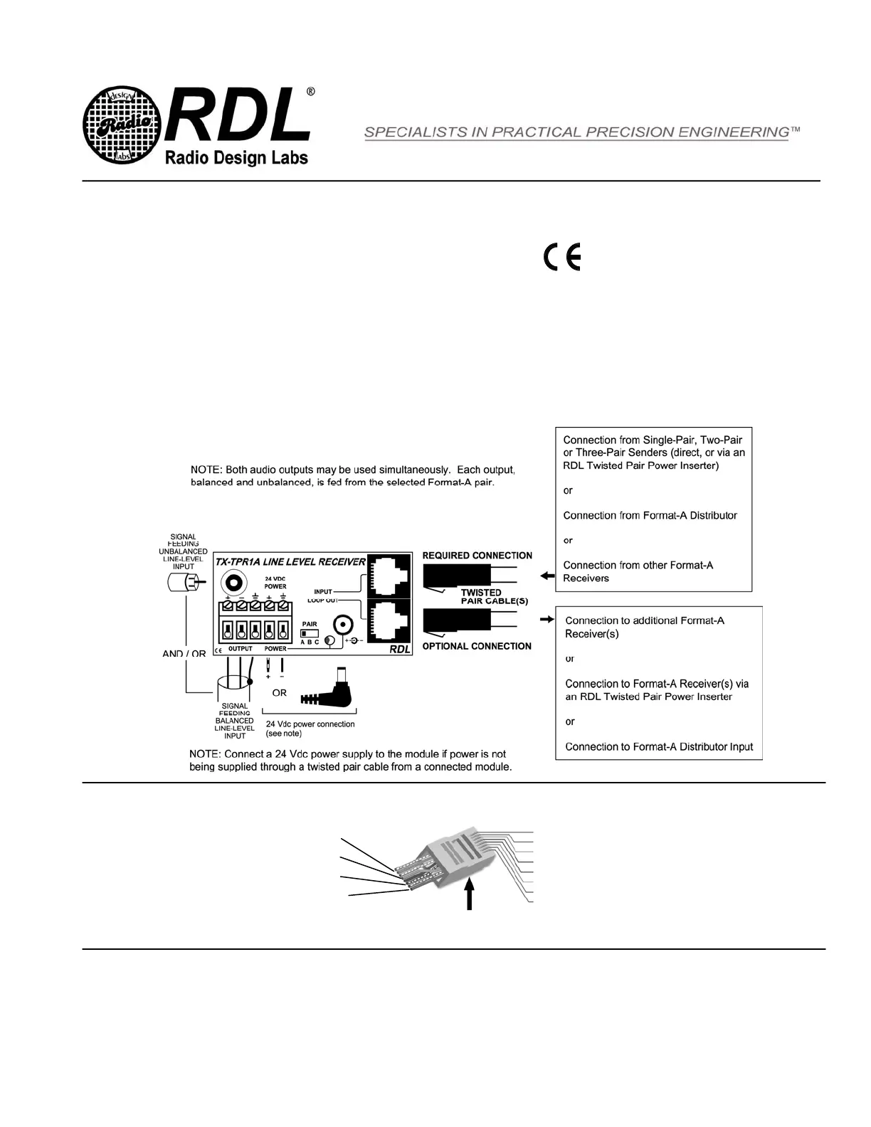
STEP 1: Connect 24 Vdc to the POWER input (terminals or jack) if this module is not being powered through the twisted pair cable from
another module, or if this module is located an excessive distance from the next powered module on the cable. Note: The front-panel power
LED will be illuminated if this module is powered. If this module is powering other modules through the cable and if there is a wiring short,
the short must be cleared then power must be turned off to this module for 10 seconds to reset the internal protection circuit.
STEP 2: Set the PAIR selector so the module is receiving signal from the desired pair A, B or C of the Format-A cable.
STEP 3: Connect the UNBAL OUT jack to a -10 dBV equipment input, and/or connect the BAL OUT terminals to a +4 dBu equipment input.
STEP 4: Connect the INPUT twisted pair cable coming from Format-A senders or distributors.
STEP 5: Connect the LOOP OUT twisted pair cable feeding additional Format-A receiver(s), if any, and mount the module.
TX
™
SERIES TWISTED PAIR
Model TX-TPR1A
Format-A Single-Pair Receiver
TYPICAL PERFORMANCE
Input: RDL TP Format-A
Input Connection: RJ45
Format-A Signal Pair Used: Switch-selectable A, B, or C
Format-A Output: RJ45 LOOP OUT
Outputs (2): 150 Ω Balanced; 1 kΩ Unbalanced
Output Connection: Detachable Terminal Block (Bal); RCA (Unbal)
Output Level: +4 dBu Bal., +22 dBu Max; -10 dBV Unbal
Frequency Response: 10 Hz to 50 kHz (+/- 0.1 dB).
THD+N: < 0.005%
Noise below +4 dBu: < 90 dB
Headroom above +4 dBu: > 18 dB
CMRR: > 80 dB (50 Hz to 150 Hz)
Indicator: Power In
Power Connections (3): Power Jack; Detachable Terminal Block; RJ45
Power Requirement: 24 Vdc @ 35 mA plus connected loads
Maximum Load Current: 165 mA
Dimensions: 3.0" (7.6 cm) W; 1.6" (4.08 cm) H; 2.09" (5.3 cm) D
Installation/Operation
EN55103-1 E1-E5; EN55103-2 E1-E4
Typical Performance reflects product at publication time
exclusive of EMC data, if any, supplied with product.
Specifications are subject to change without notice.
Radio Design Labs Technical Support Centers
U.S.A. (800) 933-1780, (928) 778-3554; Fax: (928) 778-3506
Europe [NH Amsterdam] (++31) 20-6238 983; Fax: (++31) 20-6225-287
891-7065
max
(1) + White / Green
(2) – Green
(3) + White / Orange
(4) – Blue
(5) + White / Blue
(6) – Orange
(7) + White / Brown
(8) – Brown
Pair A: Audio +4 dBu
Pair B: Audio +4 dBu
Pair C: Audio +4 dBu
Pair D: Power +24 Vdc
Tab on bottom of connector
RJ45 Standard wiring
RJ45 conductor colors shown are for 568A standard. The 568B standard may be used if the connectors at both ends of the cable are wired identically.
 Loading...