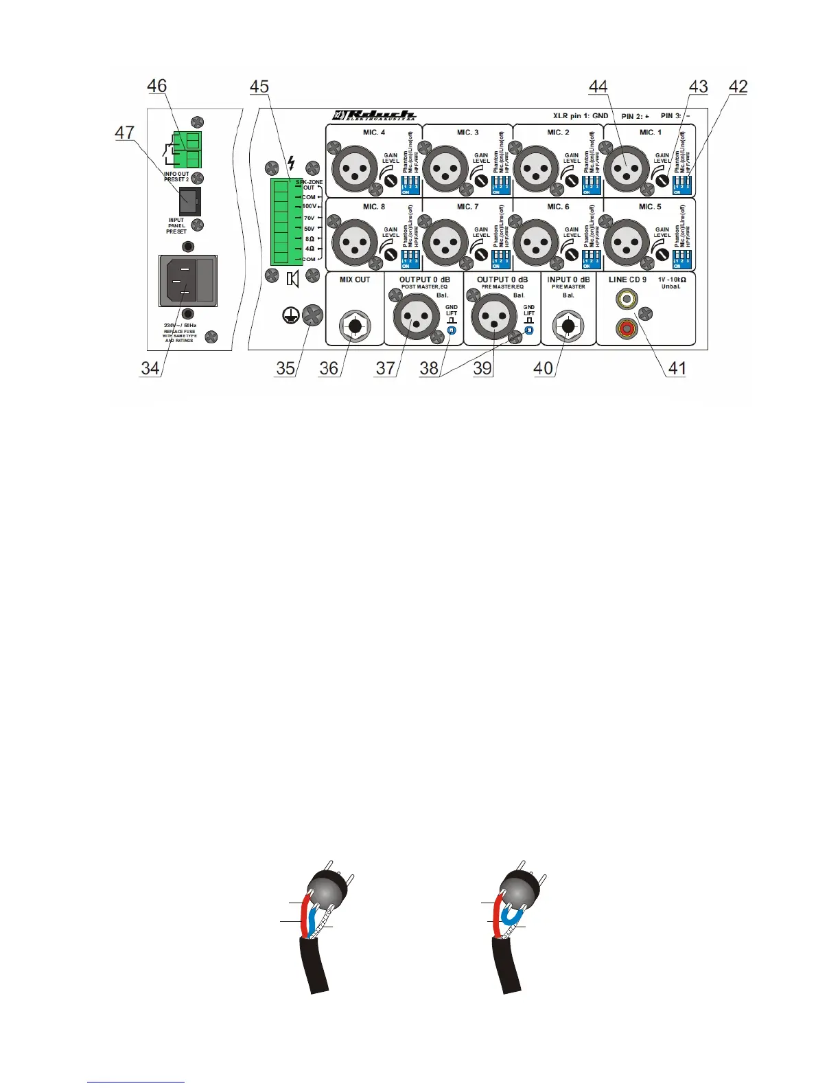
5
2 - hot (+ve)
Colt 3 & 1
asymmetric input
(
)
plug in for the cable to 5m length at the asymmetric input
Phantom power off
2 - hot (+ve)
3 - colt (-ve)
symmetrical input
(operating with phantom power
recommended)
1 - chassis ground
1 - chassis ground
4a. XLR microphone pin connection:
34- 230 V ~/ 50 Hz power socket
35- switch ground connection
36- Jack socket - MIX OUT
37- XLR socket - 0dB output befor DSP & sum
38- GND lift switch
39- XLR socket - 0dB output after DSP & sum
40- JACK socket - Input 0dB after DSP & sum
41- Cinch socket - Line CD output
42- 3 positioned switch: 1 Phantom power on/off
2 MIC / LINE switch
3 100 Hz high pass filter on / off
43- controller sensitivity of individual inputs (1-8)
44- XLR socket in each microphone input channel (1-8)
45- speaker output
46- output socket informing about Preset 2 switched on- this socket can also act to control (set off)
an additional speaker circiut that is used only in Preset 2.
47- RJ 45 socket Preset steering panel input
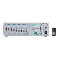
view of the back of the amplifier AMWL-9DSP1A and MWL-9DSP1A