This document is the Installation Manual for REC Alpha Panels, specifically covering the REC Alpha Pure Series and REC Alpha Pure-R Series solar panels. It provides comprehensive instructions for the terrestrial installation, operation, and maintenance of these photovoltaic modules, ensuring compliance with IEC 61215 & IEC 61730 standards.
Function Description
REC Alpha solar panels are designed to capture solar radiation and convert it into electrical energy. They are engineered for long-lasting and reliable power output, utilizing intelligent design and high-quality manufacturing processes. The manual emphasizes that correct installation and maintenance are crucial for the panels to provide decades of clean, renewable energy. The panels are certified according to IEC 61215 & IEC 61730 standards, ensuring their performance and safety for terrestrial installations.
Important Technical Specifications
The manual details technical properties for both the REC Alpha Pure Series and REC Alpha Pure-R Series.
General Data (Common to both series, with slight variations):
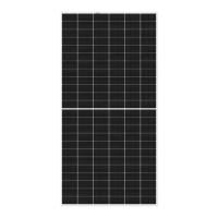
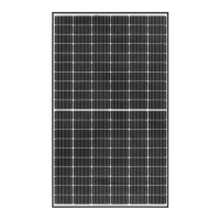
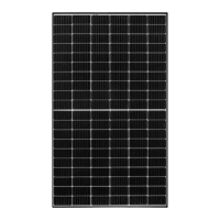
- Cell Type: Both series use half-cut REC heterojunction cells with lead-free, gapless technology. The Alpha Pure Series has 132 cells (6 strings of 22 cells in series), while the Alpha Pure-R Series has 80 cells (4-part, 4 bypass diodes).
- Glass: 3.2 mm solar glass with anti-reflective surface treatment, in accordance with EN 12150.
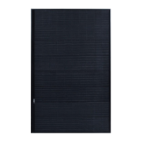
- Backsheet: Highly resistant polymer (black).
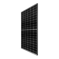
- Frame: Anodized aluminum (black).
- Junction Box: IP68 rated, lead-free, in accordance with IEC 62790. The Alpha Pure Series has a 3-part, 3 bypass diodes junction box, while the Alpha Pure-R Series has a 4-part, 4 bypass diodes junction box.
- Connectors: Stäubli MC4 PV-KBT4/KST4 (4 mm²), in accordance with IEC 62852, IP68 only when connected.
- Cable: 4 mm² solar cable, in accordance with EN 50618. Length varies: Alpha Pure Series has 1.1 m + 1.2 m, Alpha Pure-R Series has 1.7 m + 1.7 m.
- Dimensions:
- REC Alpha Pure Series: 1821 x 1016 x 30 mm (1.85 m²).
- REC Alpha Pure-R Series: 1730 x 1118 x 30 mm (1.93 m²).
- Weight:
- REC Alpha Pure Series: 20.5 kg.
- REC Alpha Pure-R Series: 21.5 kg.
- Origin: Made in Singapore.
Electrical Data (Examples for specific power outputs):
- Power Output (PMAX): Ranges from 390-410 Wp for Alpha Pure Series (STC) and 400-430 Wp for Alpha Pure-R Series (STC).
- Watt Class Sorting: 0/+5 W for Alpha Pure Series, 0/+10 W for Alpha Pure-R Series.
- Nominal Power Voltage (VMPP): For Alpha Pure Series, around 41.5-42.7 V (STC); for Alpha Pure-R Series, around 48.8-50.5 V (STC).
- Nominal Power Current (IMPP): For Alpha Pure Series, around 9.40-9.61 A (STC); for Alpha Pure-R Series, around 8.20-8.52 A (STC).
- Open Circuit Voltage (VOC): For Alpha Pure Series, around 48.6-49.0 V (STC); for Alpha Pure-R Series, around 58.9-59.7 V (STC).
- Short Circuit Current (ISC): For Alpha Pure Series, around 10.22-10.35 A (STC); for Alpha Pure-R Series, around 8.73-8.97 A (STC).
- Panel Efficiency: Ranges from 21.1-22.2% for Alpha Pure Series and 20.7-22.3% for Alpha Pure-R Series.
- NMOT (Nominal Module Operating Temperature) Electrical Data: Also provided, showing reduced power output and voltages compared to STC.
Maximum Ratings:
- Operational Temperature: -40 to +85°C.
- Maximum System Voltage: 1000 V.
- Maximum Test Load (Front): +7000 Pa (713 kg/m²) for both series.
- Maximum Test Load (Rear): -4000 Pa (407 kg/m²) for Alpha Pure Series; -3000 Pa (305 kg/m²) for Alpha Pure-R Series.
- Max Series Fuse Rating: 25 A.
- Max Reverse Current: 25 A.
Certifications:
- IEC 61215:2016, IEC 61730:2016, UL 61730.
- IEC 62804 (PID), IEC 61701 (Salt Mist), IEC 62716 (Ammonia Resistance), ISO 11925-2 (Ignitability Class E), IEC 62782 (Dynamic Mechanical Load), IEC 61215-2:2016 (Hailstone 35mm).
- Lead-free according to RoHS EU 863/2015.
- ISO 14001, ISO 9001, IEC 45001, IEC 62941.
Temperature Ratings:
- Nominal Module Operating Temperature: 44°C (±2°C).
- Temperature Coefficient of PMAX: -0.26%/°C.
- Temperature Coefficient of VOC: -0.24%/°C.
- Temperature Coefficient of ISC: 0.04%/°C.
Warranty:
- Product Warranty: 20-25 years.
- Power Warranty: 25 years.
- Labor Warranty: 0-25 years (depending on ProTrust installation).
- Annual Degradation: 0.25%.
- Power in Year 25: 92%.
Usage Features
The manual provides detailed guidance for various aspects of panel usage and installation:
- Installation Location: Panels are designed for installations up to 2000 m above sea level, with ambient operating temperatures between -40°C and +85°C. Specific hazardous locations (e.g., near flammable gas, open flames, salt water, sulfur, concentrated sunlight, harmful chemicals) are to be avoided.
- Electrical Installation:
- Application Class: Class A, Protection Safety Class II, for hazardous voltage, current, and power levels.
- System Requirements: Panels must meet the specific technical requirements of the complete system, and only panels of the same type and power class should be connected.
- String Configuration: Detailed instructions for connecting panels in a string, considering inverter manufacturer's limits, maximum system voltage, and temperature coefficients.
- Wiring Layout: Cables of the same string should be bundled to minimize voltage surges and loops. Correct DC polarity must be observed.
- Mechanical Installation:
- Fire Guidelines: Class C fire classification (UL 790), Type 2 fire classification (IEC 61730-2:2016). Requires a minimum 20 mm clearance gap between the panel and mounting surface for airflow and fire retardant roof covering.
- Orientation: Optimal mounting position is perpendicular to the sun's rays for maximum output. Panels in a string should have the same orientation and tilt.
- Securing of Panels: Panels are typically secured with rails and clamps. The manual specifies minimum clamp grip length (5-10 mm depth, 40 mm length) and torque (12-25 Nm). Panels must be secured in at least one point in each of the four marked zones (quarter divisions).
- Clamping Zones: Detailed tables and diagrams illustrate clamping zones and corresponding load ratings for continuous rails parallel to the short side, long side, and for short rails, for both Alpha Pure and Alpha Pure-R series.
- Mounting Holes: Panels can be installed using four 11 x 6.6 mm mounting holes on the underside of the panel frame, with specific bolt, nut, and washer requirements. All four mounting holes must be used, and a washer must be placed between the frame and rail.
- Slide-in Systems: When using slide-in systems, drainage holes must not be covered.
- Six-point Mounting: Specific instructions for Alpha Pure and Alpha Pure-R series, using three continuous rails and three clamps on each side, with detailed clamping zones and load ratings. The middle rail must not be on the junction box side.
- Drainage Holes: Small drainage holes (55 mm from corners) on the frame must remain open for effective water egress.
- Grounding: Local regulations must be followed. Panels have a round grounding hole near each corner, identifiable by a grounding symbol. Suitable grounding clips/lugs, conductive connections, and proper torque are required.
- Connections and Connectors:
- Connector Compatibility: Only connectors of the same manufacturer, type, and system rating are permitted.
- Cable Specifications: Minimum 4 mm² copper wires, insulated for 90°C. Cables must be secure, tight, and UV-resistant.
- Cutting Cables: Only permitted to replace factory-installed connectors with another brand for 'like-for-like' mating. Any other modification, including opening the junction box, is prohibited and voids the warranty.
- Cable Management: Cables must exit the junction box in a straight line, have a minimum bending radius of 30 mm, be secured without over-tightening, and be positioned for air circulation to prevent damage and degradation.
- Installations on Water Platforms (Annex 1):
- Site Restrictions: Only closed bodies of fresh water with salinity not exceeding 25 mS/cm at 25°C. Maximum wave height 1 m.
- Minimum Installation Height: 15 cm between water surface and lowest panel edge to shield from direct water spray.
- System Grounding: Negative system grounding is required for floating platforms.
- Panel Protection: Bird repelling devices may be installed if needed, ensuring they don't affect system performance.
- Installations using Module Level Power Electronics (MLPE) (Annex 2):
- MLPE devices can be used, but installation must follow both MLPE manufacturer's and REC's instructions.
- A minimum 15 mm gap between the MLPE device and other module architecture is required for airflow.
- A minimum 2.5 mm gap between the MLPE device and the panel backsheet is required for thermal expansion.
- Mounting holes in the panel frame must not be used for MLPE installation, and drilling extra holes is prohibited.
Maintenance Features
- Cleaning Instructions:
- Panels should be cleaned when cool (e.g., early morning) to avoid thermal shock.
- High-pressure hoses or cleaners are not permitted.
- Use deionized water (or rainwater, tap water, diluted alcohol) with a sponge, microfiber cloth, or soft brush. Mild, biological, biodegradable washing-up liquid can be used. Isopropyl alcohol (<10%) for stubborn stains.
- Avoid pressure on the panel surface.
- Wipe from top downwards with a soft rubber squeegee to remove residual water.
- Rinse with plenty of water.
- System Inspection: Regular inspection is required to ensure fasteners, electrical connections, mechanical integrity of cables, and bonding points to ground are secure, tight, and free from corrosion.
- Recycling: REC encourages local recycling of packaging and panels at the end of their useful life, in compliance with WEEE regulations in the European Union. Panels should be disposed of at appropriate collection points for electrical and electronic equipment.
- Safety: Immediately disconnect the system if deviations from standard operating conditions occur. In case of submersion on floating platforms, disconnect DC connection at the inverter immediately and do not attempt salvage while sunlight is present.