Do you have a question about the REDROTOR RC RROSD PRO V2 and is the answer not in the manual?
Policy for returning the board without soldering, checking the green LED, and warranty claims within 30 days.
Guidelines for safe operation, including high-quality soldering iron use and handling dangerous machines.
Precautions for power output limits, 6S battery configuration, and correct battery polarity.
Critical instructions on correctly connecting solder bridge pads to avoid board destruction.
The PDB is designed to operate warm to hot; avoid leaving it plugged in on the bench.
Introduction to the RROSD PRO V2 as a power distribution board and OSD for FPV experience.
Detailed list of features including power routing, regulators, filtering, and OSD information.
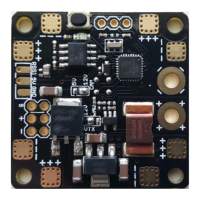
Diagram and description of connections for the top view of the RROSD PRO V2 board.
Diagram and description of connections for the bottom view of the RROSD PRO V2 board.
Details for the top connector pins: RSSI Input, +5V regulated, and Ground.
Details for the bottom connector pins: Video Signal, +12V supply, and Ground for Cam/VTX.
How to change the video mode between NTSC and PAL by holding the button on startup.
Instructions for navigating the OSD menu using the onboard button for calibration and settings.
Configuration for VTX and CAM voltage selection using solder bridges.
Instructions for soldering a 5V buzzer to the positive and negative pads.
Interpreting LED states for troubleshooting connection and signal issues.
Identifying and resolving garbled video output due to NTSC/PAL incompatibility.
| Brand | REDROTOR |
|---|---|
| Model | RROSD PRO V2 |
| Voltage Sensor | Yes |
| OSD | Yes |
| Size | 36mm x 36mm |
| Mounting Pattern | 30.5mm x 30.5mm |
| Input Voltage | 7-26V |
| Output Voltage | 5V |