EasyManua.ls Logo

ReelCraft L Series - User Manual

ReelCraft L Series
7 pages
Print Icon
To Next Page IconTo Next Page
Loading...
Ensure that only a qualified electrician installs/services this
equipment.
Ensure that power supply voltage does not exceed maximum
voltage rating of reel.
Ensure that all electrical power is removed from reel before
servicing.
A high-tension spring assembly is contained within the reel.
Exercise extreme caution.
Check for frayed and/or broken wires before each use. Pull
electrical cord from reel by grasping the electrical cord itself,
not the work device.
If an electrical malfunction should occur, remove power from
reel immediately.
Ensure that reel, electrical cord, and equipment being serviced
are properly grounded. Use an ohmmeter to check ground
continuity.
If reel ceases to unwind or rewind, remove power immediately.
Do not pull or jerk on electrical cord!
Treat and respect the reel as any other piece of machinery,
observing all common safety practices.
All cord reels with flying leads must be hard wired into the
electrical circuit to ensure proper function.
WARNING: Even low voltage can cause irreparable damage or
death! Exercise extreme caution while operating or servicing this
equipment.
SAFETY
Personal injury and/or equipment damage may result if proper safety
precautions are not observed.
Read this manual carefully before installing,
operating or servicing this equipment.
IMPORTANT
Operating Instructions
Reelcraft Industries, Inc. • 2842 E Business Hwy 30, Columbia City, IN 46725
Ph: 800-444-3134 / 260-248-8188 • Fax: 800-444-4587 / 260-248-2605
Customer Service: 855-634-9109 • reelcraft@reelcraft.com • www.reelcraft.com
Form# 1287-916 Rev: 9/2023
Dimensions
A 20 1/4”
B 19 3/4”
C 7 7/8”
D 3 7/8”
E 12 1/2”
Series L 70000 Spring Driven Cord Reels
Model Numbers:
L 70075 123 3 L 70100 123 3B L 70100 123 9G
L 70100 123 3 L 70100 123 7A L 70100 123 X
L 70075 123 3A L 70100 123 7QC L 70100
L 70075 123 3AC L 70075 123 9 L 70100 124 X
L 70100 123 3A L 70100 123 9 L 70100 124
Question and Answer IconNeed help?

Do you have a question about the ReelCraft L Series and is the answer not in the manual?

Summary

Installation Instructions

Mounting

Details on how to securely mount the cord reel unit to various surfaces.

Installing Input Electrical Cable

Procedure for connecting the main input power cable to the reel assembly.

Installing Output Electrical Cable

Procedure for connecting the electrical cable to the output side of the reel.

Maintenance Procedures

Replacing Output Cord;Work Device

Steps to safely replace the output cord or the connected work device.

Replacing Input Cord

Instructions for safely removing and installing the main input electrical cord.

Replacing Brush Holder;Brushes

Guide to replacing the brush holder and brushes assembly for proper function.

Troubleshooting and Service

Replacing Collector Assembly

Procedure for removing and installing a new collector assembly unit.

Troubleshooting Instructions

Steps for diagnosing and resolving common operational problems with the reel.

Service Instructions

General guidelines and best practices for maintaining and servicing the reel.

Overview

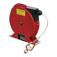
The device described in the manual is a Series L 70000 Spring Driven Cord Reel, designed for managing and dispensing electrical cords in various applications. It is a robust, industrial-grade reel that uses a spring mechanism to automatically retract the cord, ensuring a tidy and safe workspace.

Function Description:

The primary function of the cord reel is to store and dispense electrical cord, preventing tangles, damage, and trip hazards. The spring-driven mechanism provides automatic retraction, allowing the user to pull out the desired length of cord and have it retract smoothly when no longer needed. The reel is designed for both input and output electrical connections, facilitating power delivery to various tools or devices. It can be configured for top, side, or bottom-wind cable dispensing, offering flexibility in installation and use. The reel also incorporates safety features such as proper grounding and strain relief to protect both the equipment and the user.

Important Technical Specifications:

The manual lists several model numbers, including L 70075 123 3, L 70100 123 3, L 70075 123 3A, L 70075 123 3AC, L 70100 123 3A, L 70100 123 3B, L 70100 123 7A, L 70100 123 7QC, L 70075 123 9, L 70100 123 9, L 70100 123 9G, L 70100 123 X, L 70100, L 70100 124 X, and L 70100 124.

Dimensions of the reel are provided:

  • A: 20 1/4"
  • B: 19 3/4"
  • C: 7 7/8"
  • D: 3 7/8"
  • E: 12 1/2"
  • Mounting holes: Ø.516 (4 Places)

For input wiring, the manual specifies using only 12/3 or 12/4 SEOOW cable and emphasizes that the application must not exceed the electrical rating of the reel. Output cable selection should also be based on the power requirement of the apparatus to be supplied, ensuring it does not exceed the reel's electrical rating. The reel is available in 15 and 20 AMP models, indicating its capacity for different electrical loads.

Key components include:

  • Pipe Fitting 90° Elbow/Conduit Box & Cover (S159-14, 262294, 262293)
  • Strain Relief (261082, 260697-R)
  • Lock Nut (300107, 261650-1)
  • Guide Arm & Roller Assembly (S602697)
  • Base Assembly (602686)
  • Snap Ring (300007, S140-13)
  • Latch Pawl Assembly (S602694)
  • Main Shaft (262947)
  • Spring Arbor Assembly (S600621)
  • Containerized Drive Spring (S602718-80)
  • Spool & Hub Assembly (602703, S602703)
  • Gasket (262912)
  • U-Bolt (3-117440)
  • Slip Ring Bracket & Stud Assembly (602696-1)
  • Split Lock Washer (902016)
  • Adapter Plate (261577)
  • Collector Ring Assembly (S602296, S602297)
  • Cable Clamp (262371-1)
  • Grounding Cord Assembly (600283)
  • Collector Ring Cover (262938)
  • Nyloc Nut (S82-15)
  • Inlet Cord Assembly Plug (602714, 602716, 262958, 262966, 602786)
  • Outlet Box/Cord Assembly (602333-75, 602813-100)
  • Triple Tap/Cord Assembly (602712-75, 602712-100, 602713-100)
  • LED Lamp/Cord Assembly, Lamp/Cord Assembly, Outlet Cord Assembly Plug, Outlet Cord Assembly Receptacle (602709-75, 602709-100, 602710-75, 602710-100, 602711-100)
  • Flying Leads (602707-100, 602475-100)
  • Bumper Assembly (1-HR1004)
  • Polycarbonate Tube Assembly

Usage Features:

  • Installation Flexibility: The reel can be mounted on the floor, wall, or ceiling using four customer-supplied screws or bolts. The guide arm bracket can be configured for top, side, or bottom-wind cable dispensing, adapting to different installation needs.
  • Cord Management: The spring-driven mechanism ensures automatic and smooth retraction of the electrical cord, preventing tangles and maintaining an organized workspace.
  • Safety Precautions: The manual emphasizes the importance of proper grounding for the reel, electrical cord, and equipment being serviced. It warns against exceeding the maximum installation height of 16 feet (unless specified otherwise) and stresses the need for qualified electricians for installation and servicing.
  • Operation: Users are instructed to pull the electrical cord by grasping the cord itself, not the work device, and to check for frayed or broken wires before each use. In case of electrical malfunction or if the reel ceases to unwind or rewind, power must be removed immediately.

Maintenance Features:

  • Troubleshooting: The manual provides a detailed troubleshooting guide to identify problems related to defective electrical cords/work devices, brush holders/brushes, or collector assemblies. It includes steps for checking voltage at splicing connectors and continuity of input electrical cords using an ohmmeter.
  • Component Replacement: Instructions are provided for replacing key components:
    • Output Cord/Work Device: Involves extending the cord, removing the bumper stop, disconnecting the cord at splicing connectors, removing strain relief, and installing the new cord/device.
    • Input Cord: Requires removing splicing connectors from the collector assembly and installing the new cord. For GFCI receptacles, hard wiring into the electrical circuits is mandatory.
    • Brush Holder/Brushes: Involves removing wires from splicing connectors, detaching the brush holder, replacing brushes, and ensuring good contact.
    • Collector Assembly: Requires removing splicing connectors, disconnecting brush wires, removing lock nuts, snap ring, and then installing the new assembly.
  • General Maintenance: The manual advises maintaining the reel by following the provided service instructions and referring all other repairs to an authorized service person or directly to Reelcraft to avoid personal injury, equipment damage, and voiding the warranty. It also recommends turning the sheave manually until the spring is tight, backing off 2 turns, and latching it before performing certain maintenance tasks.

ReelCraft L Series Specifications

General IconGeneral
BrandReelCraft
ModelL Series
CategoryTools
LanguageEnglish

Related product manuals