RCF-230D
3
Nº Description FS
26-
29
Not used for this model
30 Number of fan speeds 3
31 Fan speed in the Auto mode:
0=The fan speed follows the cooling/heating
output, 1=The fan speed is minimum limited to
the lowest speed
1
32 Temperature compensation on AI1 0 K
33 Temperature compensation for the internal room
sensor
0 K
34 Highest permitted setpoint oset upwards. Set-
table value=0...13 K. Starting point=22°C.
13 K
35 Highest permitted setpoint oset downwards. Set-
table value=0...17 K. Starting point=22°C.
17 K
36 NO/NC digital input 1:
0=NO, 1=NC
0
37 NO/NC universal input 1:
0=NO, 1=NC
0
38 NO/NC digital output 4:
0=NO, 1=NC
1
39 NO/NC digital output 5:
0=NO, 1=NC
1
40 Manual/Auto heating output signal:
0=O, 1=Manual, 2=Auto
2
41 Manual/Auto cooling output signal:
0=O, 1=Manual, 2=Auto
2
42 Heating output signal in manual mode 0
43 Cooling output signal in manual mode 0
44 Model -
45 Version Major -
46 Version Minor -
47 Released or beta version -
48 Revision -
49 Display backlight low 10
50 Display backlight high 30
51-
63
Not used for this model
Nº Description FS
64 Basic setpoint. Settable value=5...50°C. 22°C
65 Settings, active buttons:
0 = No active buttons
1 = Only On/O button active
2 = Only Up/Down buttons active
3 = On/O and Up/Down buttons active
4 = Only fan button active
5 = On/O and fan button active
6 = Up/Down and fan buttons active
7 = All buttons active
7
66 Function to prevent user from setting manual fan
speed if fan should not run due to cooling/heating
output according to parameter 25.
0 = Not active
1 = Active
0
67 Not used for this model -
68 Not used for this model -
69 Fan kickstart. The fan will then run at 100
% for a set time when starting up (0...10
seconds).
0 s
70 Supply air temperature max limitation for
cascade control and heating control
35°C
71 Supply air temperature min limitation for
cascade control and heating control
24°C
72 Supply air temperature max limitation for
cascade control and cooling control
24°C
73 Supply air temperature min limitation for
cascade control and cooling control
12°C
74 Cascade factor between room controller and
supply air controller
3°C
75 Frost protection temperature for supply air
when supply air temperature limitation is
active
8°C
76 Activate supply air temperature limitation for:
0 = Heating control, 1 = Cooling control, 2 =
Both heating and cooling control
1
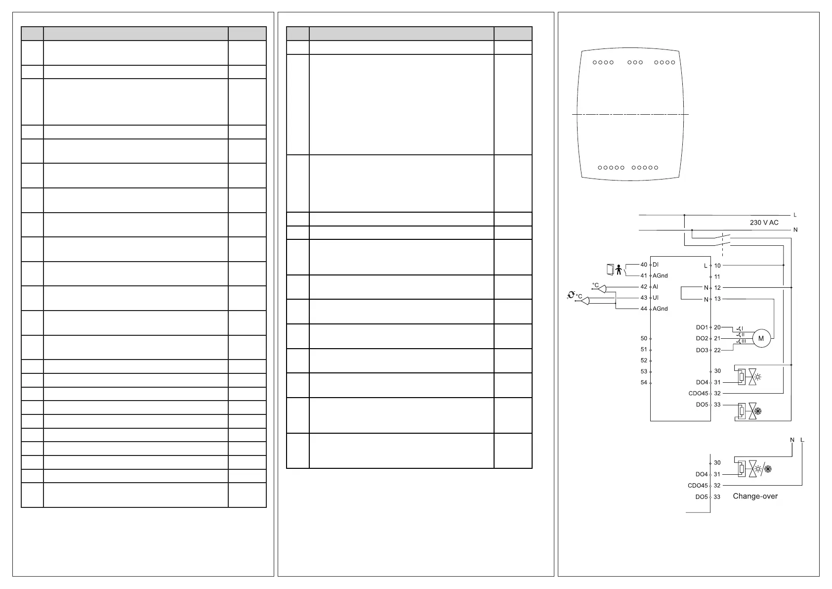
Wiring
10
20
30
LOGIC
40
50
POWER
Figure 4: Bottom plate connections
Figure 5: Connection diagram
 Loading...