2
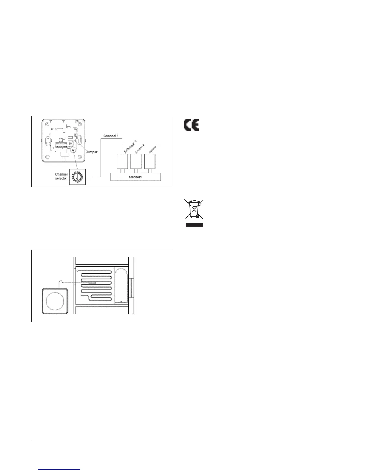
Setting up which room controller/sensor is paired with which thermal actuator
(fig. 5)
Each unit can be set to operate a specific output which in turn controls a thermal
actuator on the manifold. A selector can be accessed under the front cover of
the unit where the number of its output (i.e. its channel no.) can be set with a
screwdriver.
Please note that channels 10 to 14 are marked as A through E on the selector.
A unit set to CH1 will activate the thermal actuator connected to output 1 on the
master. The channel number can be set before power is connected to the system.
The channel set on the unit can be subsequently changed if needed. If two room
sensors are placed in the same room and set to the same channel, temperature
will be controlled by the average of the temperature recorded by both units.
For information on setting up the system, please refer to the Quick Guide in the
Installation Manual.
Fig. 5
BR1025A05a
Mounting of floor limit sensor (fig. 6)
Units with floor limit sensor have a mechanical jumper on the printed circuit
board allowing limits to be set for MIN. or MAX. temperature regulation. If set for
MAX., the limit setting will be 27°C. If set for MIN., the limit setting will be 17°C.
These temperature are fixed when used with REH BA masters unless the unit has
been allocated to a zone group controlled by a REH CT3 room controller. In this
case, the limit settings can be increased or decreased via the room controller.
The limits then set will apply to all relevant room sensors with floor limit sensor
belonging to that group. If a REH FC-BMS master is used, the limit settings can be
changed using the programming buttons on the master.
Fig. 6
BR1026A04a
Jumper connected: max. limitation
Jumper removed: min. limitation
Jumper location, see fig. 5.
Max. temperature limitation is used to prevent the floor from becoming
too warm. This may be required if special floor surfaces (e.g. solid wood)
are used. The sensor should be positioned where it can read the true
temperature of the floor and should always be within the heated area.
Min. temperature limitation is used to keep the floor surface warm,
irrespective of room temperature. In tiled bathrooms or pool areas, for
example, water will dry more quickly if the floor surface is kept warm. The
sensor should be positioned where it can read the true temperature of the
floor and should always be within the heated area.
To ease replacement, we recommend that all floor sensors are mounted in a tube
positioned between two heating pipes. The inner end of the tube should be
sealed, and the floor sensor cable led back to the bottom of the wall. If required,
the sensor cable can be extended up to 30 m with standard installation cable.
See the Installation Manual for further instructions.
Maintenance
The unit is maintenance free.
Keep the air vents (openings) on the unit clean and unobstructed at all times.
Certications
CE marking
REHAU Ltd hereby declares that the product conforms with the following
Directives of the European Parliament and of the Council:
• CE marking: 1993/68/EEC
• EMC - electromagnetic compatibility: 2004/108/EC
• R&TTE - Radio Equipment and Telecommunications Terminal Equipment
and the mutual recognition of their conformity: 1999/5/EC
• RoHS - restriction on the use of certain hazardous substances: 2011/65/
EU
• WEEE - waste electrical and electronic equipment: 2012/19/EU
Applied standard(s)
EN 61000-6-2, EN 61000-6-3
Additional for WLxR3-29
EN 300 220-1, EN 300 220-2, EN 301 489-3, EN 301 489-1, EN 50371
Disposal and recycling
Recycling of packaging
Protect the environment by disposing of the packaging in accordance with
local regulations for waste processing.
Disposal of the product
Equipment containing electrical components must not be
disposed of together with domestic waste.
It must be collected separately along with other electrical and
electronic waste according to local and currently valid legislation.
Technical Specifications (REHxT3)
Purpose of control...................Wired electronic room controller/sensor for
controlling hydronic floor heating and cooling
Connection type ................................2-wire, 5 V, communication bus
Cable type ...............................Standard installation cable ≥0.25 mm²
Cable length ...................Up to 300 m with max. 100 m between two units
Control principle ..............................PI (4°C P-Band) - PWM or ON-OFF
Ambient operating temperature ........................................0/+40°C
Power drain ...........................................Without backlight <1 mA
With backlight <30 mA
Temperature range . . . . . . . . . . . . . . . . . . . . . . . . . . . . . . . . . . . . . . . . . . . . . . . . . . . +5/+40°C
Functions (REH DT3) .................... .Auto, comfort, setback, frost protection
Functions (REH CT3) ...................Timed or manual operation, zone control
Room sensor ...........................................................Internal
Floor limit sensor ............................Can be connected, max 30 m cable
Mounting method..................For mounting direct on wall or in wall socket
Enclosure rating ...........................................................IP 21
Dimensions .........................................H/86.0, W/86.0, D/25.5 mm
REHAU Limited
Hill Court, Walford, Ross-on-Wye, Herefordshire, HR9 5QN
Tel. +44 1989 762600· Fax +44 1989 762601
enquiries@rehau.com · www.rehau.uk
 Loading...