RESOL SP1
Overvoltage protection
© RESOL 07249 Sp1.monen.indd
| 2
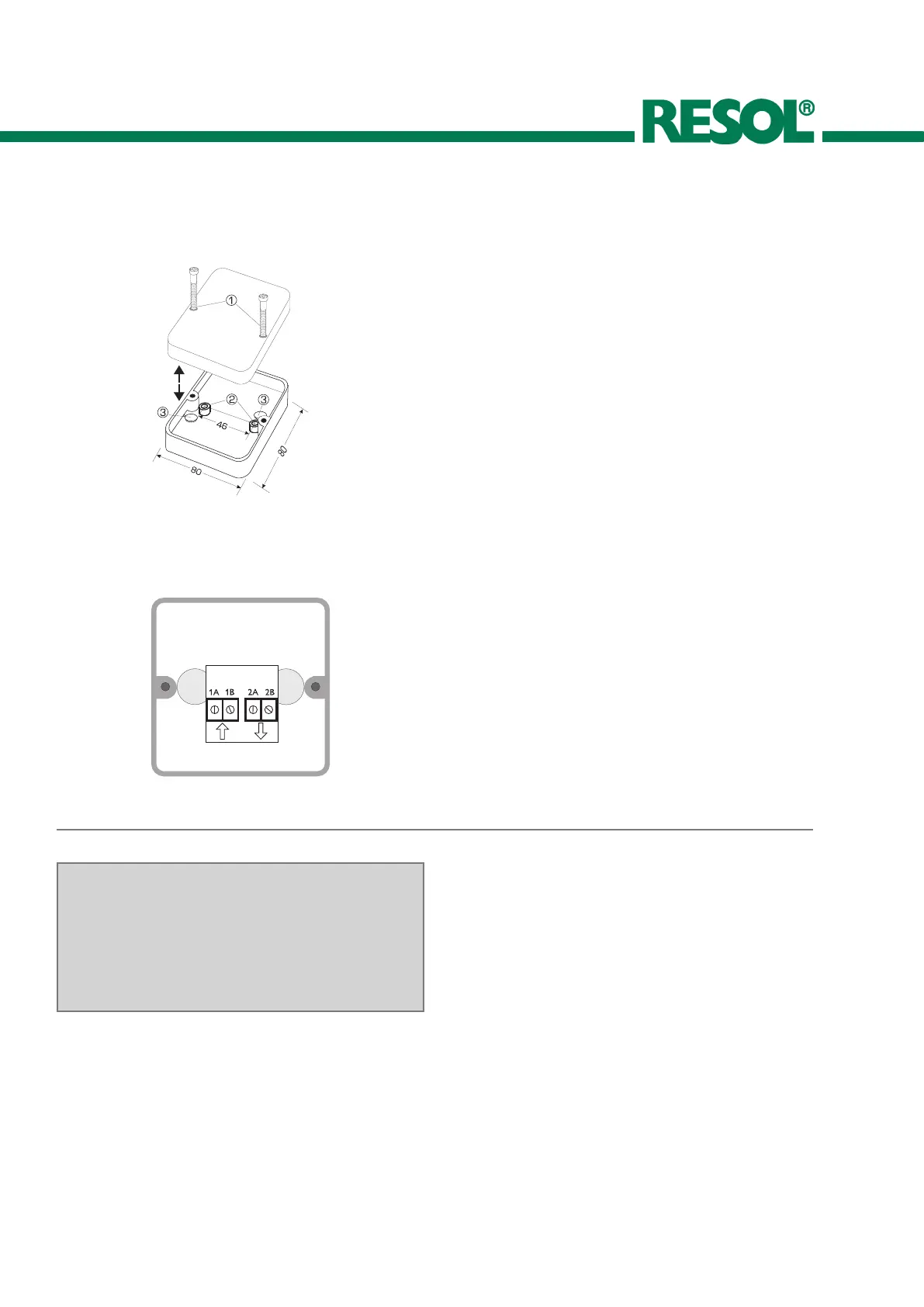
1. Mounting
After the screws have been loosened (1), the upper part of
the housing can be removed from the connecting box. With
the aid of the two holes (2) the lower part of the connecting
box has to be fastened to a plane and stable surface. The
protective caps (3) have to be removed from the bottom
and inserted into the screw holes.
2. Electrical connection
Pierce the cable glands with a pointed object. Insert the
cables into the holes and pull them slightly back, such that
the rubber layer is slightly turned to the outside. Thus the
device is protected against moisture. Connect the sensor
cable to the terminals 1A and 1B, and the connecting box
cable to the terminals 2A and 2B. If polarity has to be con-
sidered (this is required for the irradiation sensor CS10!),
the cables with the same designation have to be connected
to the same designations (1A and 2A as well as 1B and 2B
are the two connection paths).
Sensor cables carry safety extra low voltage (SELV) and must
not be placed in a gland together with cables carrying 230 V.
If the connecting box is used outdoors, it is recommended
to pierce the condensation water hole at the bottom after
the device has been installed.
Your Distributor:
RESOL - Elektronische Regelungen GmbH
Heiskampstraße 10
45527 Hattingen / Germany
Tel.: +49 (0) 23 24 / 96 48 - 0
Fax: +49 (0) 23 24 / 96 48 - 755
www.resol.de
info@resol.de
Please note:
The design and the specifications are to be changed without
notice.
The illustrations may differ from the original product.
Reprinting / copying
This mounting- and operation manual including all parts
is copyrighted. Another use outside the copyright re-
quires the approval of RESOL - Elektronische Rege-
lungen GmbH. This especially applies for copies, translati-
ons, micro films and the storage into electronic systems.
Editor: RESOL - Elektronische Regelungen GmbH
Important notice:
We took a lot of care with the texts and drawings of this
manual and to the best of our knowledge and consent. As
faults can never be excluded, please note: Your own calcu-
lations and plans, under consideration of the current stan-
dards and DIN-directions should only be basis for your
projects. We don´t offer a guarantee for the completeness
of the drawings and texts of this manual - they only repre-
sent some examples. They can only be used at your own
risk. No liability is assumed for incorrect, incomplete or
false information and the resulting damages.
 Loading...