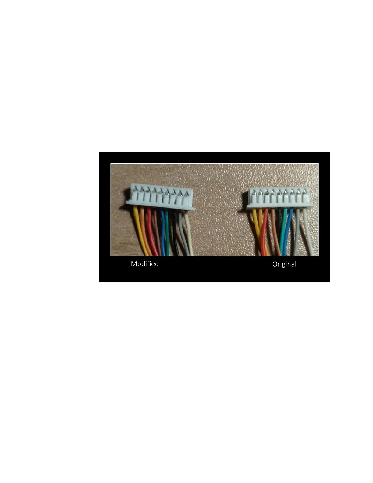
▪ Using a needle, lever up the plastic pins of the 9-
pin connector that hold pin 5 and 7 in place,
while simultaneously pulling the wire out.
• Note: working from left to right (with the
yellow pin 1 on the left), pin 5 is black and
pin 7 is blue.
▪ Push the wires into their new positions, with
blue now in position 5, and black in 7.
o For PCB version 1.5c:
▪ Disconnect the 9-pin cable from the “VCC on 7”
port of the circuit board and reconnect to “VCC
on 5”
o NOTE: This modification will also allow limited
compatibility with the Sega Mega Drive.