36/60 Installation
Bosch Rexroth AG, A6VE Series 65 and 71, RE 91616-01-B/10.2014
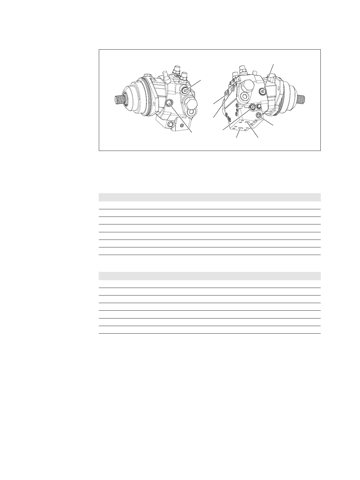
A
T
1
T
2
B
S
X
Bre
M
B
M
A
Fig. 14: Port overview A6VE with HZ7 control and integrated counterbalance valve(BVI),
working line ports below
Table 13: Ports A6VE Series 65
Ports
1)
p
max
[bar]
2)
Status
A, B Working line port 450 O
T
1
Drain port 3 X
3)
T
2
Drain port 3 O
3)
G Synchronous control 450 X
X Pilot signal (HP, HZ, HA1T/HA2T) 100 O
X Pilot signal (HA1 and HA2) 3 X
M
1
Stroking chamber measurement 450 X
Table 14: Ports A6VE Series 71
Ports
1)
p
max
[bar]
2)
Status
A, B Working line port 500 O
T
1
Drain port 3 X
3)
T
2
Drain port 3 O
3)
G Synchronous control 500 X
X Pilot signal (HP, HZ, HA1T/HA2T) 100 O
X Pilot signal (HA1 and HA2) 3 X
M
1
Stroking chamber measurement 500 X
1)
The measuring system and thread size can be taken from the installation drawing.
2)
Depending on the application, short-term pressure spikes can occur. Keep this in mind when
selecting measuring equipment and fittings.
3)
Depending on the installation position, T
1
or T
2
must be connected (see chapter 7.3 “Installation
position” on page 27)
O = Must be connected (plugged on delivery)
X = Plugged (in normal operation)
 Loading...


