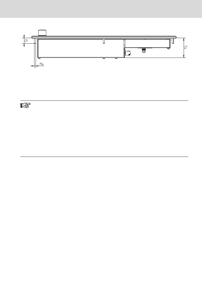
Fig. 10-15: VDP 60.3: Left view
10.3 Mounting Cut-out
Mount the operating display as follows:
Loss of degree of protection IP 65!
The housing in which the operator display is installed, has to fulfil
the following conditions:
● free from impurities
● sufficient mechanical strength and flatness
These criteria influence the required degree of protection IP to a
great extent.
Further required measures are to be taken depending on the mount-
ing location, e. g. the stabilization of the mounting frame.
1. Create a mounting cut-out with 8 holes, diameter 5 mm, according to the
illustrations "Mounting dimensions" on the following pages.
2. Remove the paper strip from the seal on the rear side of the front panel.
3. Insert the operator display from the front into the cut-out. The mounting
bolts M4 are inserted into the drilled holes, see fig. 10-16 "Position of the
mounting bolts" on page 26.
4. Fasten the display by screwing the nuts at the rear side of the mounting
bolts, see fig. 10-16 "Position of the mounting bolts" on page 26.
VDP 16.3, VDP 40.3, VDP 60.3
Bosch Rexroth AG
Assembly, Disassembly and Electrical Installation
DOK-SUPPL*-VDP*XX.3***-IT03-EN-P
25/53
 Loading...