8-2 Connection Techniques Rexroth IndraDyn A
8.2 Power Connection
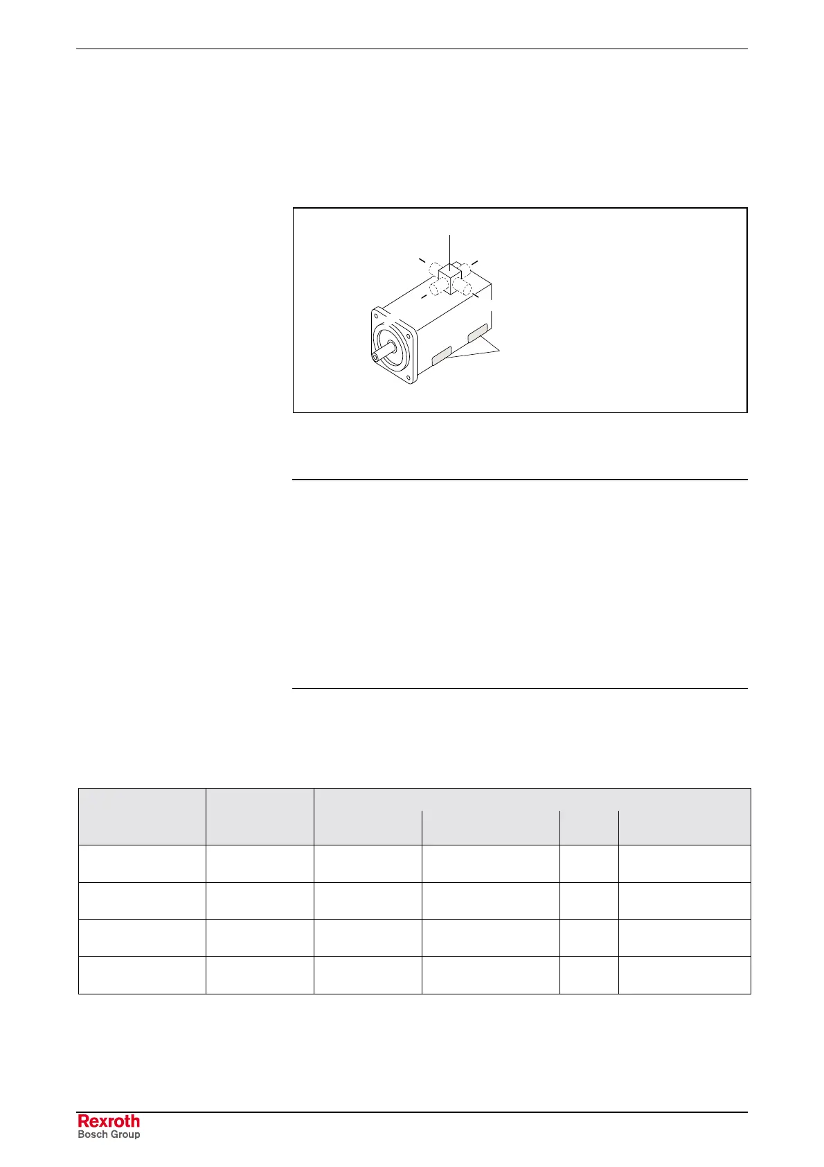
The connection of power to IndraDyn A motors is made at the top of the
motors and can be established performed via a flange socket or a
terminal box.
B-side
right
left
A-side
top
bottom
mounting feet
(only in mounting style B35)
Lage_Leistungsanschluss_EN.EPS
Fig. 8-1: Position of the power connection
Note:
• When choosing the connection option “flange socket”,
please note that the power cable must be equipped with a
plug with a bayonet connection.
• When choosing the connection option “terminal box”,
please note that the power cable must be terminated with
ferrules on conductors U, V and W, and the PE (ground)
conductor must be equipped with a ring terminal.
• The design of the power cable also depends on the drive
device used. Please observe the documentation of the
drive device.
Overview
Terminal box
Motor frame size
MAD/MAF
Flange socket
U-V-W
Max. cross section of
power cable
∅PE
Connection thread
100 INS480 Ferrules 10mm² M6
see motor dimension
sheet
130 INS380 Ferrules 25mm² M8
see motor dimension
sheet
160 INS380 Ferrules 35mm² M8
see motor dimension
sheet
180 not available Ring terminal 50mm² M12
see motor dimension
sheet
Fig. 8-2: Overview power connection

 Loading...

