Rexroth IndraDyn A Connection Techniques 8-3
8.3 Power Connection via Flange Socket
Stecker
plug
Antriebs-
regelgerät
drive contoller
A
B
C
M
3
Bremse/brake
(optional)
U
E
H
F
1
2
3
GN/YE
D
A
B
C
D
E
H
F
G
nicht belegt
not in use
PTC
A
B
C
G
F
H
E
D
J
K
L
A
B
C
G
F
H
E
D
J
K
L
Flanschdose
flange socket
INS0480
Flanschdose
flange socket
INS0380
Flanschdose
flange socket
1
2
G
L
8
7
6
5
MAx_Power_Connect1.EPS
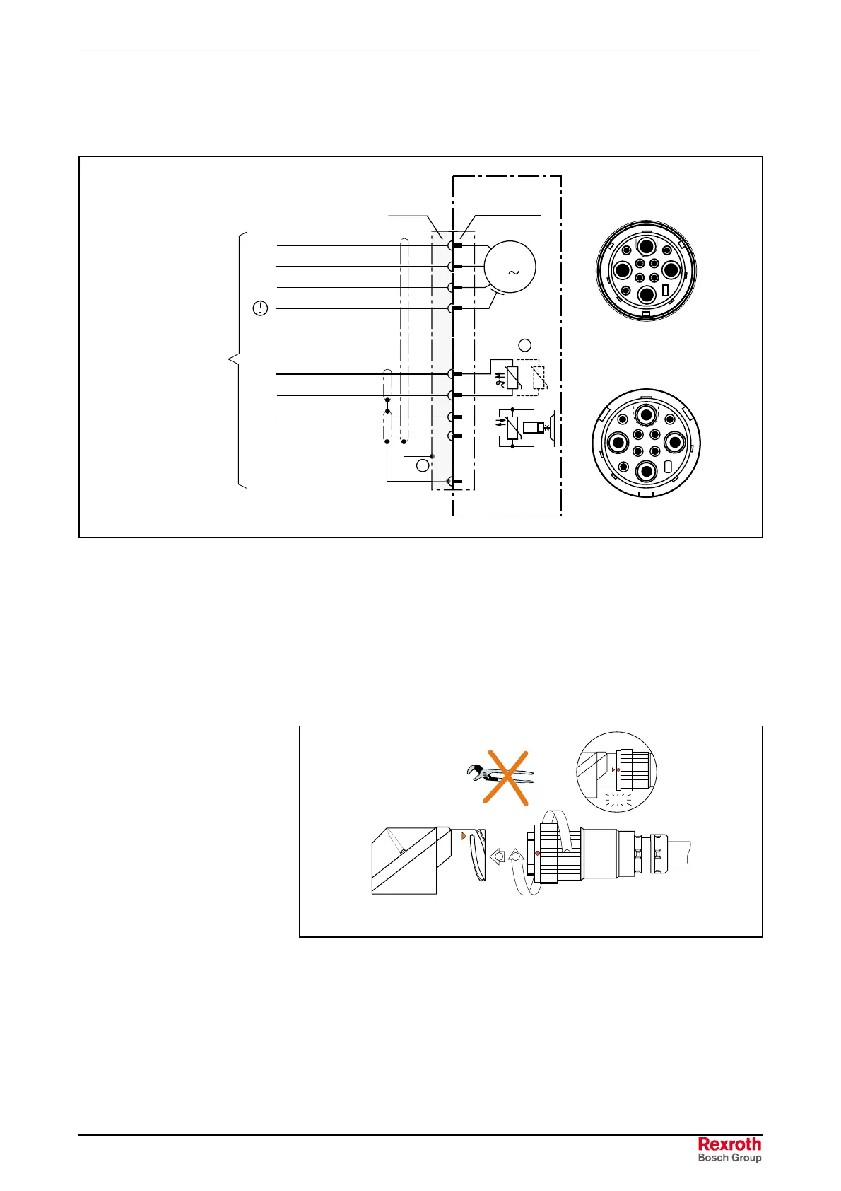
(1): The shield connection made in the plug via the cable grip.
(2): Only one PTC sensor is wired. The leads for the spare sensor are
found within the plug housing.
Fig. 8-3: Layout of power connection in flange socket
Flange Socket
The power connectors of the IndraDyn A motors are equipped with flange
sockets with bayonet connections.
1
INS0380
INS0381
2
MAx_Power_Plug.EPS
Fig. 8-4: Power connector
1. Insert the plug into the flange socket; pay attention to the coding.
2. Manually tighten the union nut until it audibly locks in.
3. The red marks on the flange socket and the plug align when the
bayonet connection is properly locked in.

 Loading...

