8-4 Connection Techniques Rexroth IndraDyn A
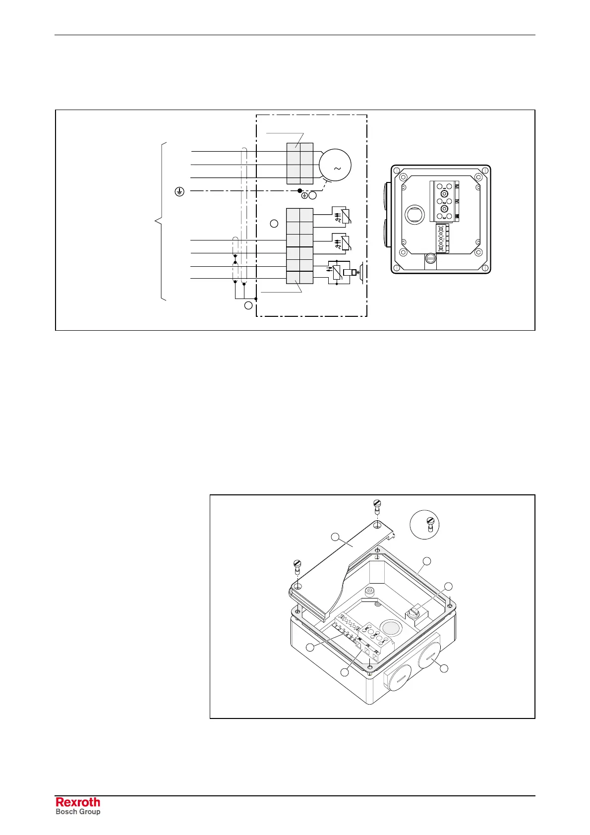
8.4 Power Connection via Terminal Box
Antriebs-
regelgerät
drive controller
M
3
Bremse/brake
(optional)
U
1
2
3
GN/YE
U1
V1
W1
4
3
2
1
PTC
Klemmbrett
terminal block
PTC
Klemmleiste
terminal strip
1
6
5
3
2
7
8
5
6
MAx_Power_Connect2.EPS
(1): Electrically-conducting connection to the motor housing
(2): The shield connection must be properly made in the cable via the
cable grip after the cable grip is threaded into the terminal box
(3): Only one PTC sensor is monitored. Connect the spare sensor only if
necessary, e.g. because of failure of the first sensor.
Fig. 8-5: Layout of power connection in terminal box
Terminal box
IndraDyn A motors designed for drive combinations with higher DC bus
voltages - up to 750V
DC
– are equipped with a terminal strip or terminal
block in the terminal box for the connection of cables with ferrules.
1
2
4
6
5
3
4 x
MAx_Power_Box.EPS
(1): Cover (2): Seal (gasket)
(3): PE (ground) connection (4): Cable entry
(5): U-V-W power connection (6): Terminal strip
Fig. 8-6: Terminal box

 Loading...

