Rexroth IndraDyn A Connection Techniques 8-9
The cables for connecting the motor encoder and the drive device must
have a compatible plug on the motor side.
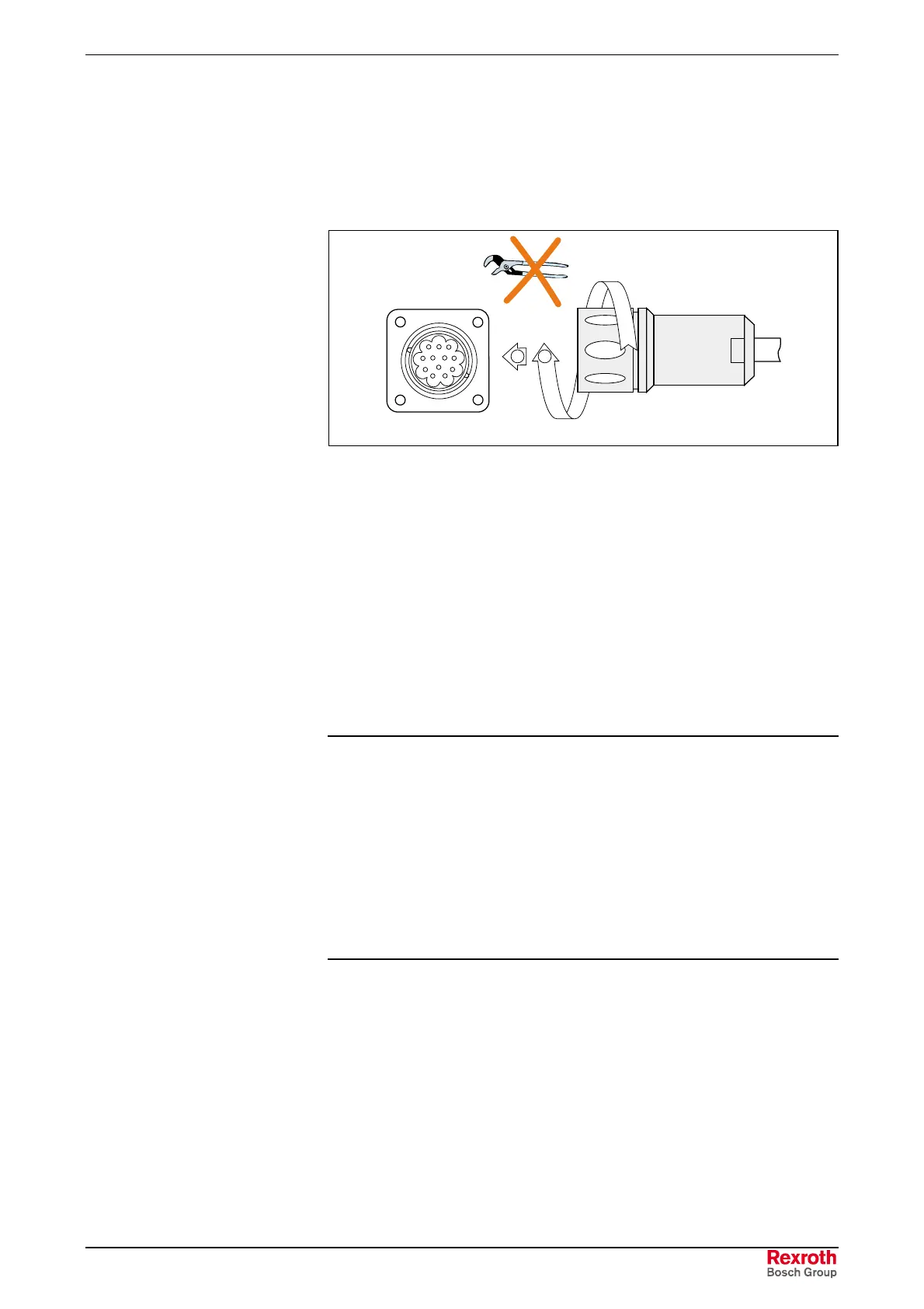
The motor encoder`s flange socket and the cable plug from the drive
controller are mirror images of one another. They are connected without
tools, i.e. by hand.
Heed the mechanical codings of the flange sockets.
8
7
6
5
4
3
2
1
9
12
11
10
1 2
MAx_Encoder_Connect.EPS
Fig. 8-14: Example of the encoder connection
1. Insert the plug into the flange socket paying attention to the coding.
2. Manually tighten the union nut.
8.8 Temperature Sensors
IndraDyn A motors are equipped with two PTC temperature sensors, type
KTY84-130, which are permanently mounted in the motor windings. For
additional information on temperature sensors, refer to Chapter 9.9
“Motor Temperature Overview”.
Note:
• For the connection layouts, refer to Figs. 8-3 and 8-5 at the
beginning of this chapter.
• Notice the correct polarity when using the sensor for
external temperature measurement (see Fig. 9-16).
• The signal lines to the PTC sensors are routed to the
controller via the motor power cable.
• Only one sensor at a time is connected to and evaluated by
the drive controller. The function of the spare sensor
cannot be guaranteed.

 Loading...

