8-10 Connection Techniques Rexroth IndraDyn A
8.9 Holding Brake
The motor holding brake is triggered either directly through the drive
device or externally.
Note:
• For the connection layout, refer to Figs. 8-3 and 8-5 at the
beginning of this chapter.
• Control voltage is +24 V
DC
(+/-10%)
• Take note of the functional differences of an electrically-
clamping vs. an electrically-releasing brake (see Chapter
9.10 “Motor Holding Brake”).
8.10 Motor Cooling
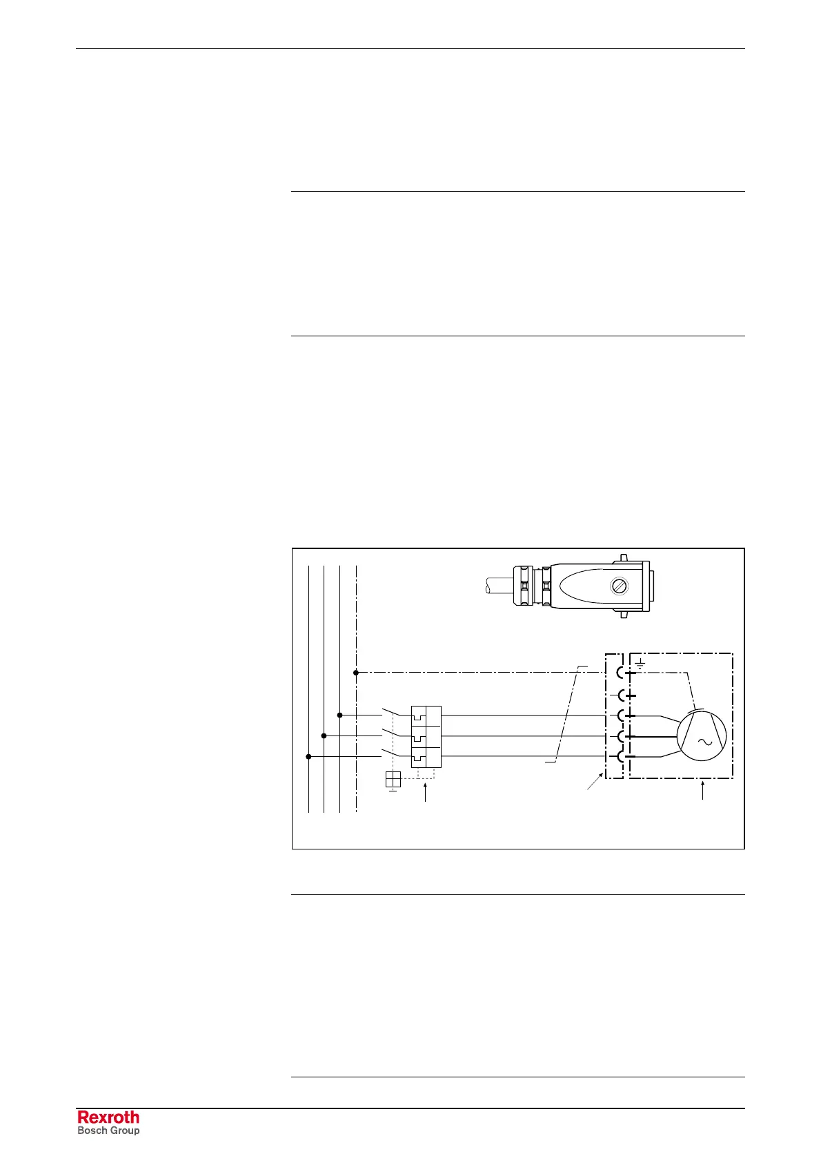
Blower Connection
The motor blower is connected to the power supply system via a cable
and motor-protecting switch, and it functions independent of the drive
device.
PE
0,75 1,5 mm
2
0,75 1,5 mm
2
L2L1
I>>I>>I>>
0,75 1,5 mm
2
L3
1
2
3
M
3
Netzanschluß
mains connection
Ø 6...10 mm
Schutzschalter
protective switch
Steckverbinder
plug-in connector
INS0705
Lüfter
blower
4
INS0705
Blower_Connect.EPS
Fig. 8-15: Blower connection diagram
Note:
• To establish the connection, the blower plug must be
opened and closed.
• The electric connection may only be established by skilled
personnel. Please observe the safety notes.
• The seal of the plug housing may not be compromis.
• The machine manufacturer selects the motor protecting
switch and the electrical protection. Please observe the
regulations in the country of installation.

 Loading...

