9-22 Application Notes Rexroth IndraDyn A
9.13 Bearing and Shaft Loads
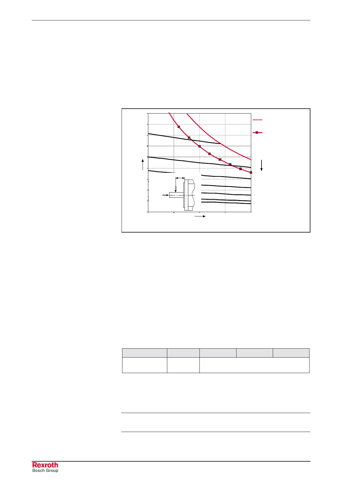
During operation, both radial and axial forces act upon the motor drive
shaft and, thus, upon the bearings. Machine design and motor type must
be carefully adapted to make sure that the specified load limits are not
exceeded.
Radial Load, Axial Load
x/mm
Fradial/N
Welle glatt
Shaft plain
Welle mit Passfeder
Shaft with keyway
n
mittel
min
-1
n
average
min
-1
F
axial
F
radial
x
F
radial_max
AHbsp_WB.EPS
Fig. 9-24: Example of a shaft load diagram
The maximum permissible radial force F
radial_max
depends on the following
factors:
• Shaft-breaking stress
• Point of force application, x (see Fig. 9-24)
• Shaft design (smooth; with keyway)
The permitted radial force F
radial
depends on the following factors:
• Arithmetic mean speed (n
mean
)
• Point of force application x (see Fig. 9-24)
• Bearing Lifetime
Only low axial shaft loads are permitted on IndraDyn A motors.
MAD/MAF 100 130 160 180
permissible axial
load [N]
30 50
Fig. 9-25: Axial load
The permitted axial load applies for all installation positions. Therefore,
the motors are not suitable for machine elements that generate axial
loading of the motors (e.g. helical driving pinions).
Note: Avoid impermissible axial loads or jolting of the motor drive
shaft.
The acceleration and deceleration times can be ignored in the calculation
if the time during which the drive is operated at a constant speed is
Maximum Permissible Radial
Force F
radial_max
Permissible Radial Force F
radial
Permissible Axial Force F
axial
Mean Speed

 Loading...

