Rexroth IndraDyn A Application Notes 9-23
significantly greater than the acceleration and deceleration times. In the
exact calculation of the mean speed according to the following example,
the acceleration and deceleration times are taken into account.
n
t
t
H1
t
1
t
B1
t
11
t
H2
t
2
t
B2
t
22
n
1
n
2
Average.EPS
111B11H
1B
1
111H
1
m1
tttt
t
2
n
tnt
2
n
n
+++
⋅+⋅+⋅
=
n
1m
: mean speed in section 1 n
2m
: mean speed in section 2
n
1
: processing speed n
2
: processing speed
t
H1
: acceleration time t
H2
: acceleration time
t
1:
processing time t
2:
processing time
t
B1
: deceleration time t
B2
: deceleration time
t
11
: standstill time t
22
: standstill time
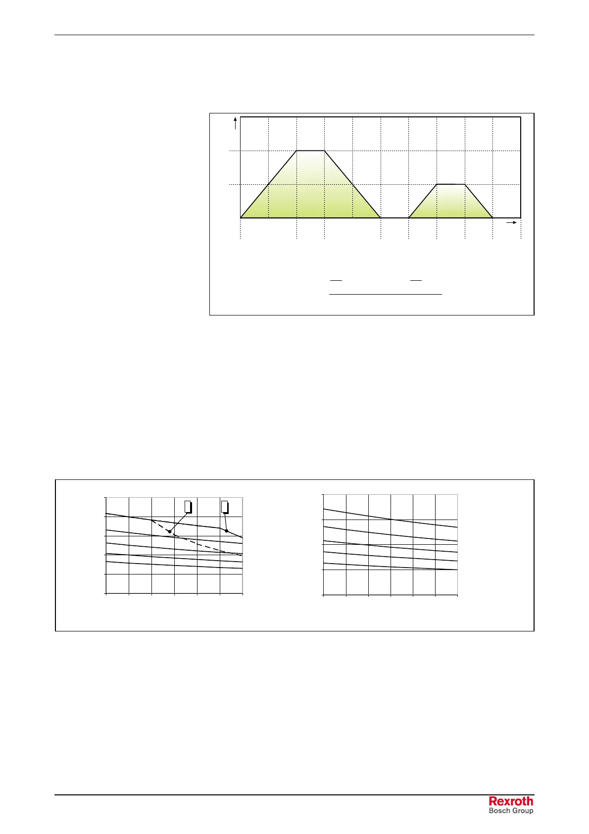
Fig. 9-26: Mean speed
A complete operating cycle can consist of several sections with different
speeds. In this case, the average is to be generated from all the sections.
Type "N" / "R"
n
m
= 1000 min
-1
n
m
= 2000 min
-1
n
m
= 4000 min
-1
n
m
= 8000min
-1
2
n
m
= 500 min
-1
1
0
1
2
3
4
5
0 102030405060
x [mm]
Fr [kN]
Type "H"
n
m
= 500 min
-1
n
m
= 1000 min
-1
n
m
= 2000 min
-1
n
m
= 4000 min
-1
n
m
=10000min
-1
0
0,5
1
1,5
2
0 102030405060
x [mm]
Fr [kN]
Wellenbelastung MAx100.EPS
"N": Standard bearings
“R“: Bearing for coupling attachment
”H”: High-speed bearing
(1): Load limit for drive shaft without keyway
(2): Load limit for drive shaft with keyway
n
m
: Mean speed
Fig. 9-27: Shaft load, Motor-frame size 100 (L
h
=30,000 operating hours)
Shaft Load, Size 100

 Loading...

