12-4 Connection System Synchronous Motors MKD
19.05.2004 Version7.0 DOK-MOTOR*-MKD*******-PR07-EN-P
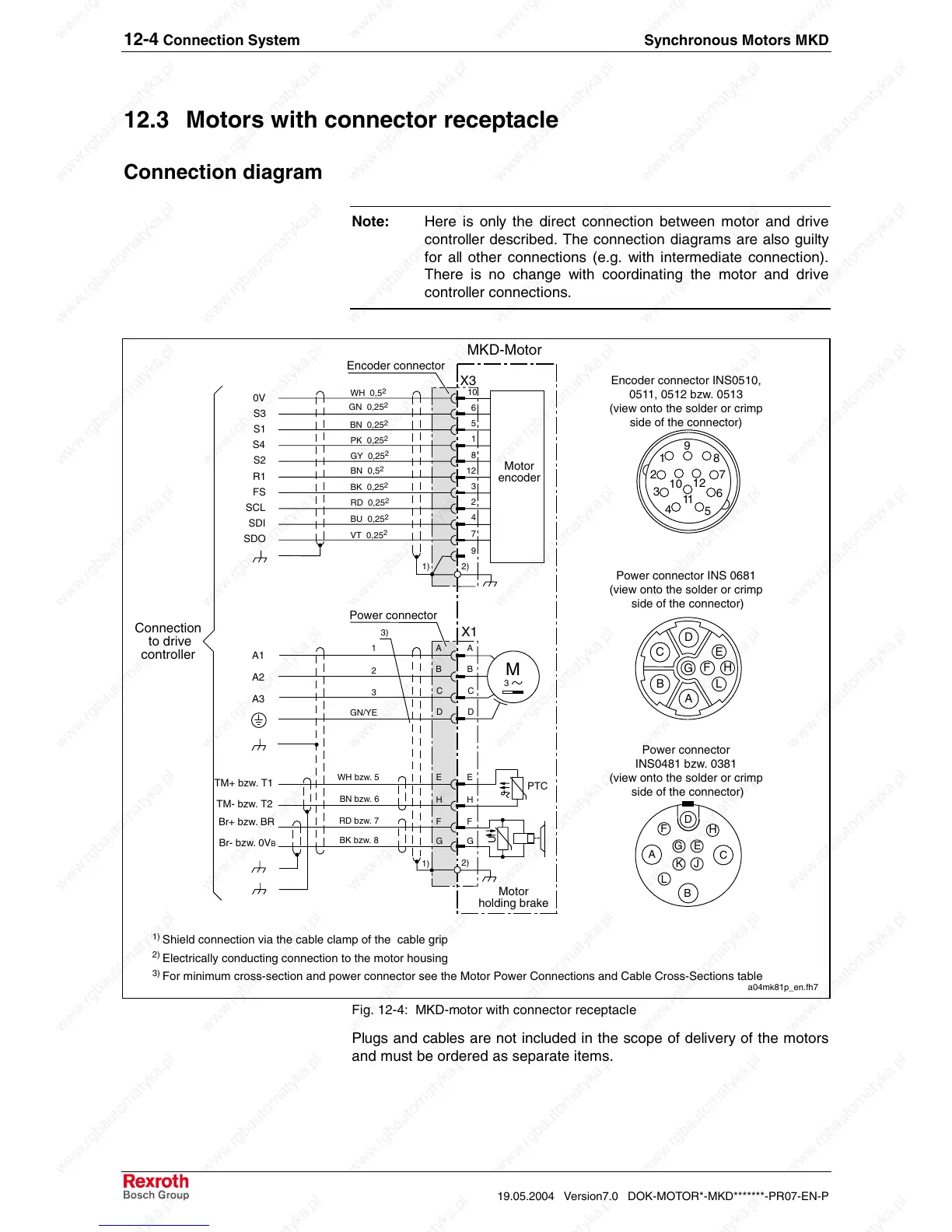
12.3 Motors with connector receptacle
Connection diagram
Note: Here is only the direct connection between motor and drive
controller described. The connection diagrams are also guilty
for all other connections (e.g. with intermediate connection).
There is no change with coordinating the motor and drive
controller connections.
A
B
C
A1
A2
A3
M
3
Motor
holding brake
TM- bzw. T2
PTC
U
MKD-Motor
Motor
encoder
E
H
F
G
1
2
3
GN/YE
TM+ bzw. T1
Br- bzw. 0V
B
Br+ bzw. BR
VT 0,25
2
BU 0,25
2
RD 0,25
2
BK 0,25
2
GY 0,25
2
PK 0,25
2
BN 0,25
2
GN 0,25
2
WH 0,5
2
BN 0,5
2
10
6
5
1
8
12
3
2
4
7
0V
S3
S1
S4
S2
R1
FS
SCL
SDI
SDO
Connection
to drive
controller
a04mk81p_en.fh7
3)
BK bzw. 8
RD bzw. 7
BN bzw. 6
WH bzw. 5
9
D
A
B
C
D
E
H
F
G
X3
X1
2)
2)
1)
1)
A
B
C
D
E
HF
G
L
B
H
F
L
C
A
D
E
K J
G
1
2
3
4
5
6
7
8
9
10
11
12
Encoder connector INS0510,
0511, 0512 bzw. 0513
(view onto the solder or crimp
side of the connector)
Power connector
INS0481 bzw. 0381
(view onto the solder or crimp
side of the connector)
1)
Shield connection via the cable clamp of the cable grip
2)
Electrically conducting connection to the motor housing
3)
For minimum cross-section and power connector see the Motor Power Connections and Cable Cross-Sections table
Power connector
Encoder connector
Power connector INS 0681
(view onto the solder or crimp
side of the connector)
Fig. 12-4: MKD-motor with connector receptacle
Plugs and cables are not included in the scope of delivery of the motors
and must be ordered as separate items.
 Loading...


