Synchronous Motors MKD Assembly 15-5
DOK-MOTOR*-MKD*******-PR07-EN-P Version7.0 19.05.2004
Encoder cable
Power cable
16
2,5 Nm
2,5 Nm
1,3 Nm
a05mk81p_en.fh7
Plugin terminal
Part. No.: 259 698
Plugin terminal
Part. No.: 259 700
16
X1
X2
X3
90
90
Connector
Part. No.: 236 813
Crimping contact
10 x Part. No.: 260 765
98
6
X5
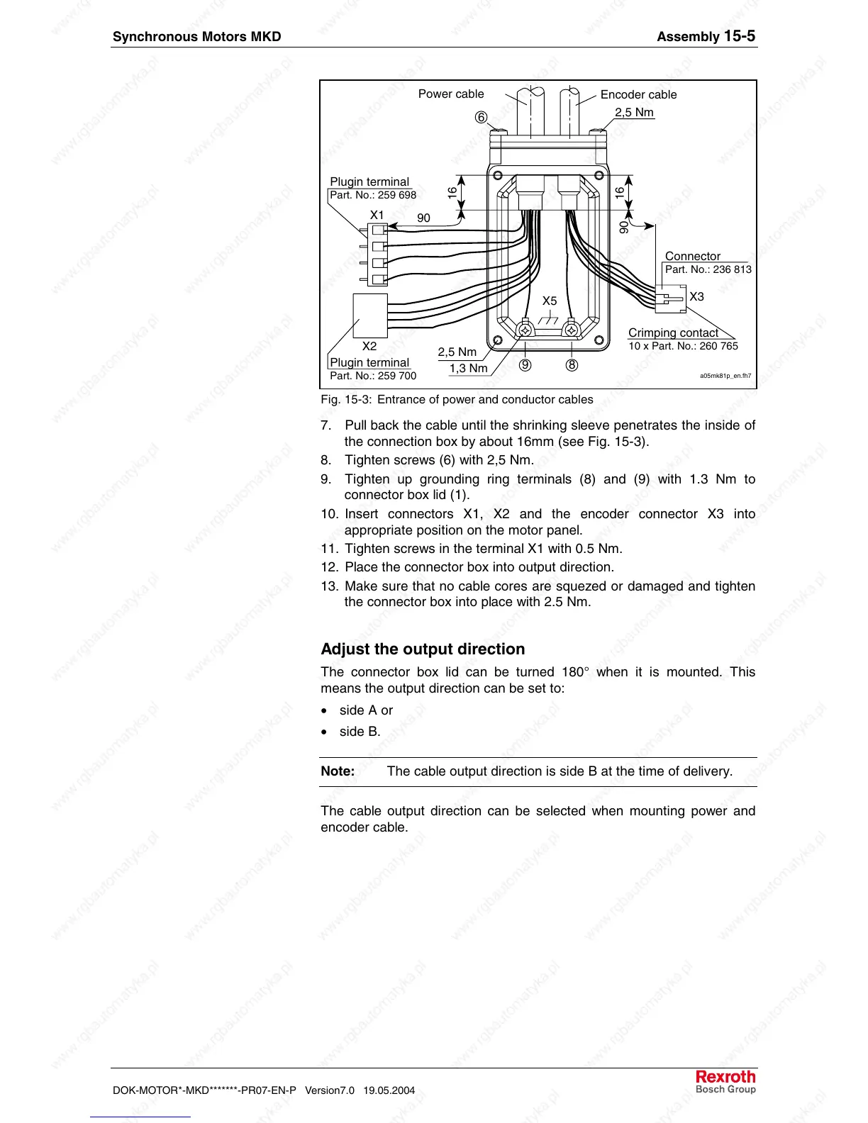
Fig. 15-3: Entrance of power and conductor cables
7. Pull back the cable until the shrinking sleeve penetrates the inside of
the connection box by about 16mm (see Fig. 15-3).
8. Tighten screws (6) with 2,5 Nm.
9. Tighten up grounding ring terminals (8) and (9) with 1.3 Nm to
connector box lid (1).
10. Insert connectors X1, X2 and the encoder connector X3 into
appropriate position on the motor panel.
11. Tighten screws in the terminal X1 with 0.5 Nm.
12. Place the connector box into output direction.
13. Make sure that no cable cores are squezed or damaged and tighten
the connector box into place with 2.5 Nm.
Adjust the output direction
The connector box lid can be turned 180° when it is mounted. This
means the output direction can be set to:
• side A or
• side B.
Note: The cable output direction is side B at the time of delivery.
The cable output direction can be selected when mounting power and
encoder cable.
 Loading...


