9-10 MKD090 Synchronous Motors MKD
19.05.2004 Version7.0 DOK-MOTOR*-MKD*******-PR07-EN-P
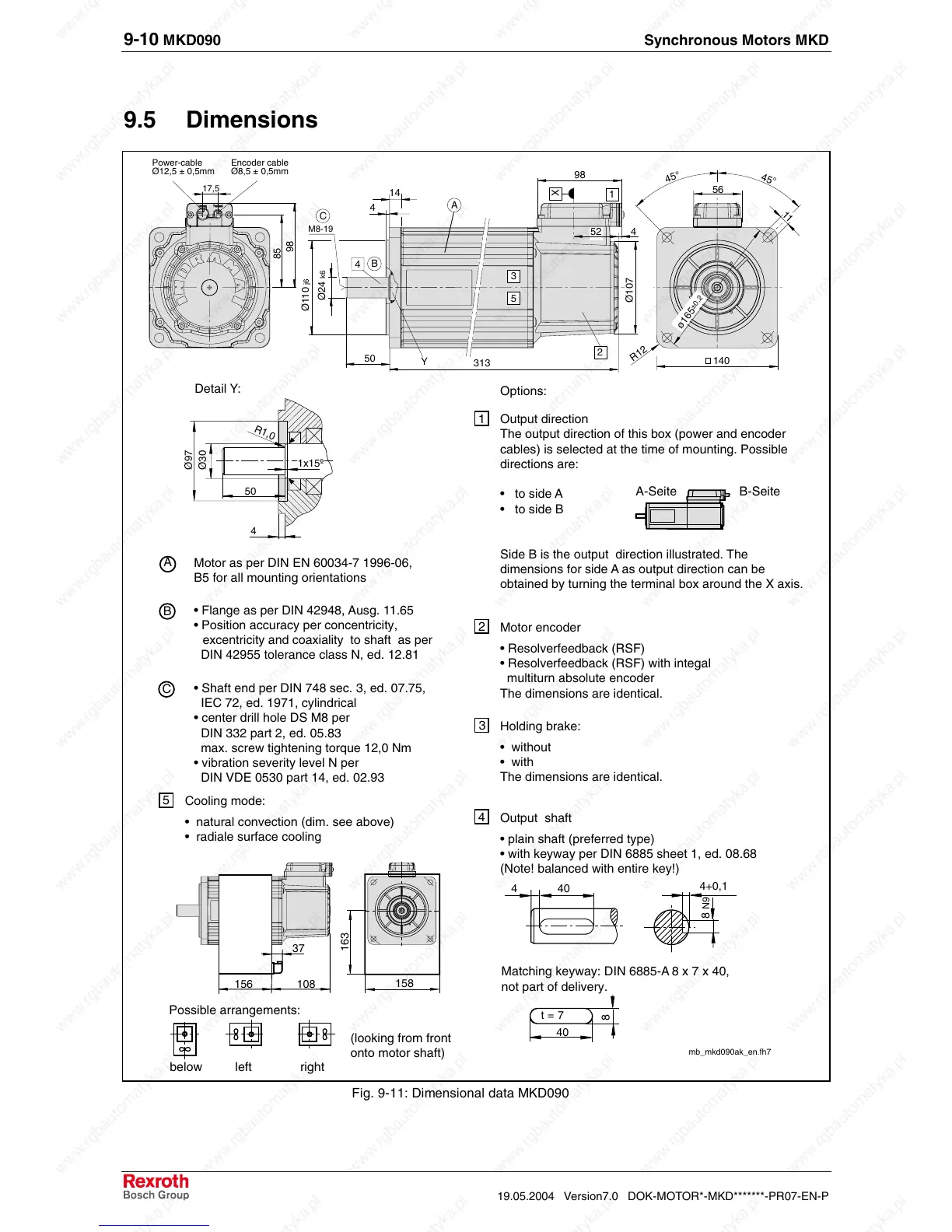
9.5 Dimensions
Power-cable
Ø12,5 ± 0,5mm
Encoder cable
Ø8,5 ± 0,5mm
Detail Y:
98
4
X
52
56
45°
45°
B
C
A
Motor as per DIN EN 60034-7 1996-06,
B5 for all mounting orientations
• Flange as per DIN 42948, Ausg. 11.65
• Position accuracy per concentricity,
excentricity and coaxiality to shaft as per
DIN 42955 tolerance class N, ed. 12.81
• Shaft end per DIN 748 sec. 3, ed. 07.75,
IEC 72, ed. 1971, cylindrical
• center drill hole DS M8 per
DIN 332 part 2, ed. 05.83
max. screw tightening torque 12,0 Nm
• vibration severity level N per
DIN VDE 0530 part 14, ed. 02.93
mb_mkd090ak_en.fh7
40
4+0,1
8
N9
Options:
4
2
1
3
4
40
8
t = 7
Matching keyway: DIN 6885-A 8 x 7 x 40,
not part of delivery.
A-Seite B-Seite
R12
below left right
Possible arrangements:
(looking from front
onto motor shaft)
Cooling mode:
• natural convection (dim. see above)
• radiale surface cooling
5
158
163
156
37
108
17,5
85
98
313
A
14
4
Ø107
Ø110
j6
Ø24
k6
B
M8-19
4
C
50
Y
2
1
3
5
140
11
ø165
±0,2
Output direction
The output direction of this box (power and encoder
cables) is selected at the time of mounting. Possible
directions are:
• to side A
• to side B
Side B is the output direction illustrated. The
dimensions for side A as output direction can be
obtained by turning the terminal box around the X axis.
Motor encoder
• Resolverfeedback (RSF)
• Resolverfeedback (RSF) with integal
multiturn absolute encoder
The dimensions are identical.
Holding brake:
• without
• with
The dimensions are identical.
Output shaft
• plain shaft (preferred type)
• with keyway per DIN 6885 sheet 1, ed. 08.68
(Note! balanced with entire key!)
Ø30
Ø97
R1,0
1x15º
50
4
Fig. 9-11: Dimensional data MKD090
 Loading...


