Form I-MAPSIII&IV, Page 24
5.0 Mounting
(cont'd)
5.4.3 Duct Furnace Curb Sections, Option JH30 for Cabinet C and
Option JH25 for Cabinet B (cont'd)
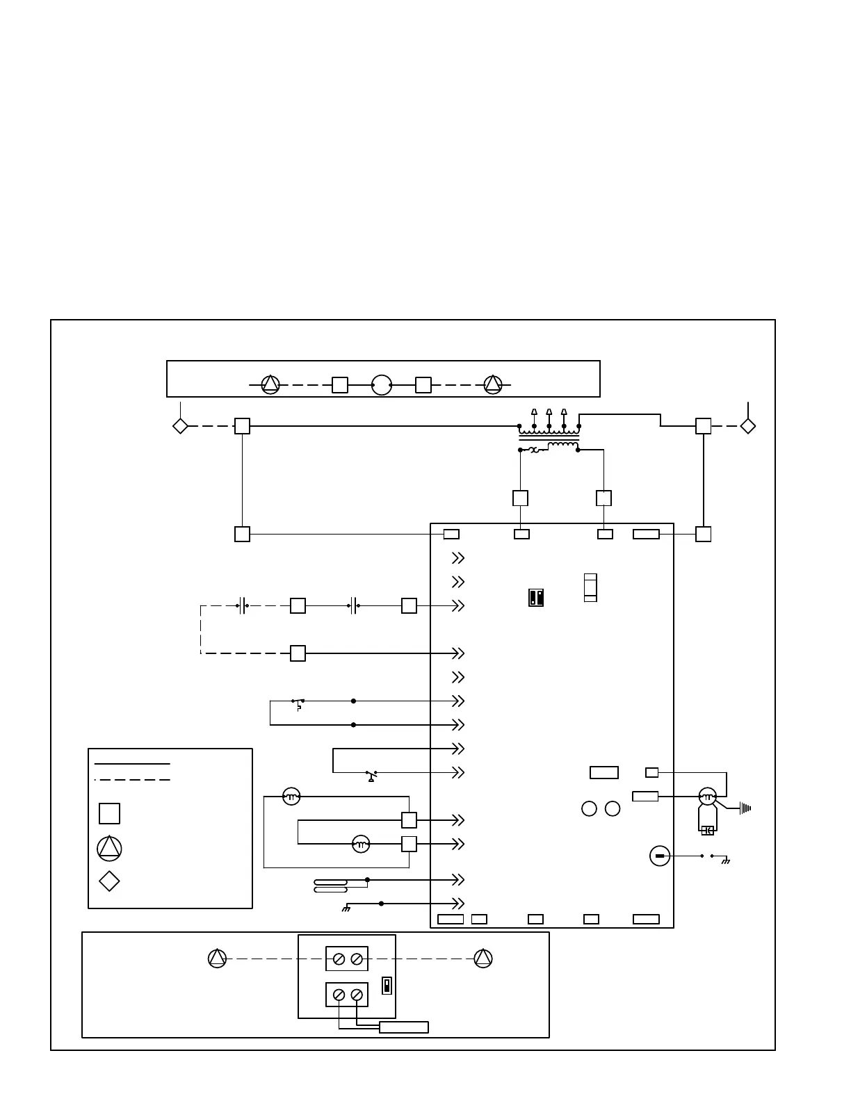
Duct Furnace Operation
The duct furnace can only be energized after the main unit DSI control has enabled
operation of the integral heat section and the remote temperature controller's sensor
initiates a call for heat. When both of these conditions are met, the duct furnace will
be energized to operate at full re only.
FIGURE 11C - Wiring Connections for Optional Curb Duct Furnace
41
FLAME
ELECTRODES
BR
BK OR R
FLAME GROUND
R
R
BR
R
NEUTRAL
P1-7
P1-9
BL
#2 GAS VALVE
BR
PRESSURE SWITCH
(PS3)
Y
Y
Y
R
P1-4
BL
64
63
BR
P1-2
P1-5
P1-3
P1-6
REMOTE TEMPERATURE CONTROLLER
CONTROL TERMINAL IN T7079
DUCT FURNACE ENABLE
RELAY CONTACTS
BK OR R
NOCOM
J4
LIMIT CONTROL
34
RR
33
R
46
R
Y
R
P3-1
P1-8
P3-4
32
Y
P3-2
P3-3
P3-5
DUCT FURNACE ENABLE
RELAY COIL (319)
40 40
BL
7
300
CR8
BR
41
INTERNAL CONTROL FAULT OR NO POWERSTEADY OFF
(VM2)
MOTOR
VENTER
CAPACITOR
UNDESIRED FLAME (VALVE OPEN & NO CALL FOR HEAT)
(DS2)
WEAK FLAME
FLAME SENSED
DSI CONTROL
DUCT FURNACE
FAST FLASH
SLOW FLASH
STEADY ON
YELLOW LED
OK
LED
G
TRANSFORMER
SPARK
Y
LED
FLAME
TEST
NEUTRAL
IND
BR/W
SPARK GAP
BK
W
BR
BK
G
GRD
NORMAL OPERATION CALL FOR HEAT
NORMAL OPERATION NO CALL FOR HEAT
PRESSURE SWITCH DOES NOT CLOSE WITHIN 30
PRESSURE SWITCH IS CLOSED BEFORE VENTER IS
ENERGIZED
IN LOCKOUT FROM FAILED IGNITIONS OR FLAME LOSSES
SW1
LED FLASH CODES
LIMIT SWITCH OPEN
SECONDS OF VENTER ENERGIZED
2 FLASH
1 FLASH
3 FLASH
FAST FLASH
STEADY ON
4 FLASH
Y
R
C
W
G
GREEN LED
3.0 AMP
FUSE
ATO OR ATC
SEC COM NEUTRAL
L1
BREAKER
96
Y
CIRCUIT
88
BK
W
(TX5)
97
Y/W
Y/W
24 V
TRANSFORMER
240V
OGYR
75 VA
DSI
O
89
BK
L1L1L1
SEC NEUTRALCOM
W
BL
BR
8988
BK
BK
88 89
FACTORY WIRING
FIELD WIRING
TERMINAL BLOCK -- DUCT FURNACE
TERMINAL BLOCK -- HIGH VOLTAGE
TERMINAL BLOCK -- LOW VOLTAGE
COMPARTMENT
COMPARTMENT
(See below and unit diagram.)
#1 GAS VALVE
BL
BL
BR
(See unit wiring diagram.)
(See unit wiring diagram.)
SET ST1 SWITCH
TO HEAT POSITION
(MOUNT IN OUTSIDE AIRSTREAM)
TEMPERATURE SENSOR
T7079 REMOTE
TEMPERATURE
CONTROLLER
J1 SENSOR
J2 24VAC
ST1
2120
Remote
Temperature
Controller
5.4 Mounting on a Roof Curb (cont'd)
The duct furnace requires a separate gas line; gas connection is 1/2". See gas sup-
ply entrance location in the illustrations. Refer to Paragraph 9.2.1.2 for gas supply
piping and pressure requirements. The Size 300 duct furnace burner operates only at
high re. Manifold pressure is 3.5" w.c.; see Paragraph 9.2. The high temperature limit
control functions the same as described in Paragraph 9.2.4.
Field wiring is required. Check the wiring diagram for requirements. Follow the wiring
diagram in FIGURE 11C to connect the eld-supplied wiring.
Option JH30 Duct
Furnace Installation

 Loading...
