Form I-MAPSIII&IV, P/N 222917R9, Page 45
FIGURE 23 - Optional
Hot Gas Bypass Valve
Check Hot Gas Bypass Valve Setting - On the circuit with a hot gas bypass valve,
connect a pressure gauge to the suction line and block the entering air to the evapora-
tor coil. Suction pressure will drop, and the hot gas bypass valve should begin to open
at approximately 115 psi and will be fully open at 95 psi. When the valve begins to
open, it will be hot to the touch (see caution below).
CAUTION: Do not touch the hot gas bypass valve when
operating. Use caution when checking and adjusting the
valve. Wear appropriate safety gear.
If pressure needs to be adjusted, remove the cap and turn the adjusting stem clock-
wise to increase the pressure setting or counterclockwise to decrease the pressure
setting. Make adjustments in small increments. Allow ve minutes between adjust-
ments for the system to stabilize. When nished, replace the cap on the adjustment
stem and remove the pressure gauge.
Modulating Reheat,
Option AUR1
With modulating reheat, a sensor monitors the air temperature as it leaves the reheat
coil. Based on a potentiometer setpoint and the sensor signal, the board will open or
close a refrigerant bypass valve. Changing the amount of refrigerant hot gas being
added to the refrigerant liquid before it enters the pre-cool coil will “modulate” the func-
tion of the pre-cool and reheat coils to provide the desired leaving air temperature.
8.0 Controls
NOTE: See control details and instructions in
Form CP-MAPS-D15/D16 included with the unit and
available at www.RezSpec.com.
All systems have a unit-mounted, IQ controller that is pro-
grammed to control cooling, dehumidication, and/or heating
based on discharge air temperature, outdoor air temperature,
dewpoint, and/or enthalpy depending on which Model and
options were ordered. The system control option is identied
as either Option D15, programmed for neutral air/discharge
air control, or Option D16, programmed for space control with
discharge air reset.
The integrated LCD display (*BACview) will show the current
discharge air temperature, outdoor air temperature, dewpoint,
and enthalpy; which outputs are enabled; and the mode of
operation. The control allows the user to change setpoints,
change prop bands, and adjust the time clock.
Control Option D16 will also have a wall temperature sensor.
If ordered as Option CL77 with Option D15, it will also have a
wall temperature sensor. Or, if ordered with Option RB4, there
is a handheld display/control module with most of the same
functions as the unit-mounted display.
A brief description of control functions follows in this section.
For additional information and to make adjustments, see the
more detailed control instructions in Form CP-MAPS D15/
D16.
The IQ controller has an integral time clock for occupied/unoc-
cupied modes and supports BACnet (over MSTP or ARCnet)
and LonWorks protocols. The control also provides or moni-
tors the air proving switch, low limit protection, anti-cycle pro-
tection, minimum on/off times, phase loss protection, optional
dirty lter sensor, gas valve modulation on systems with a gas
heat section, and electric staging on systems with electric
heat.
8.1 Cooling/Dehumidication/Heating Control
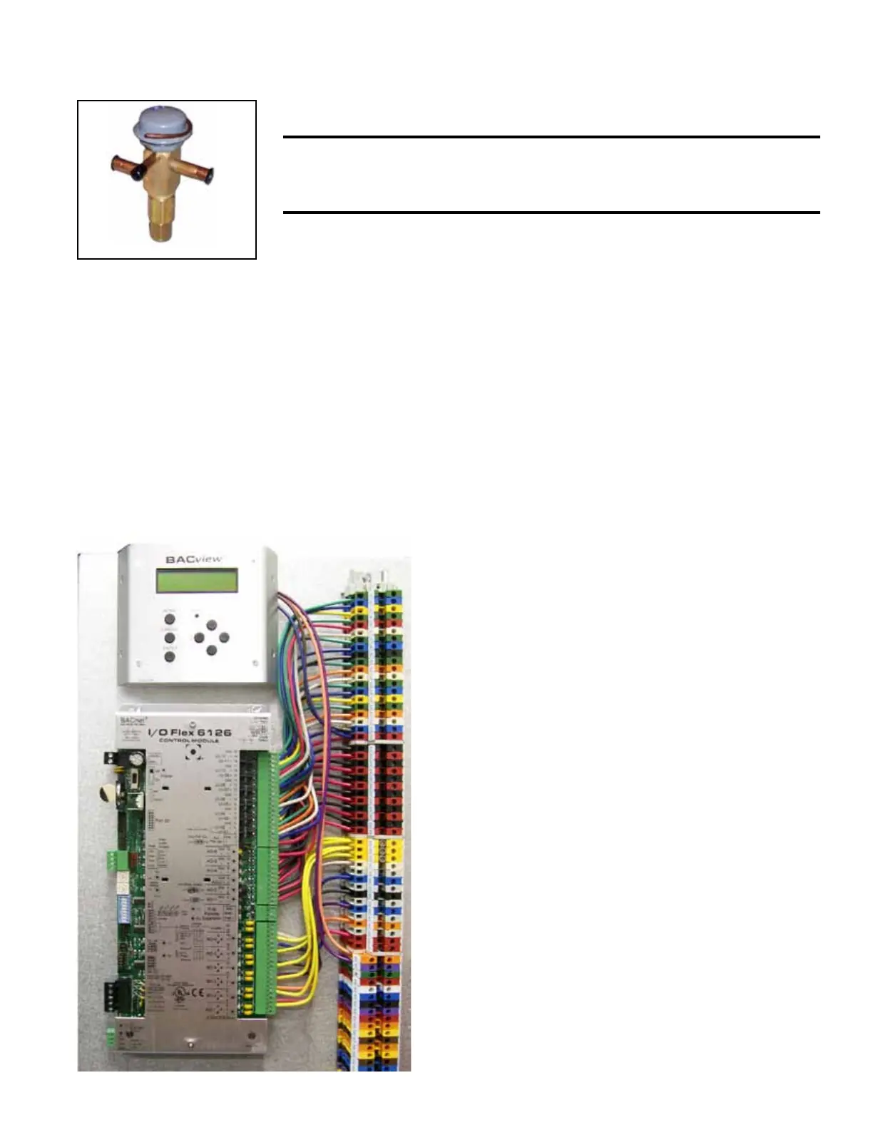
FIGURE 24 - Controller and BacView
Display in Electrical Compartment

 Loading...
