Form I-MAPSIII&IV, Page 62
9. Optional
Equipment
(cont'd)
9.2.2 Gas Heat Module Ignition Systems (cont'd)
9.2 Gas Heat -
Models RDCB,
RDDB, RDCC,
RDDC (cont'd)
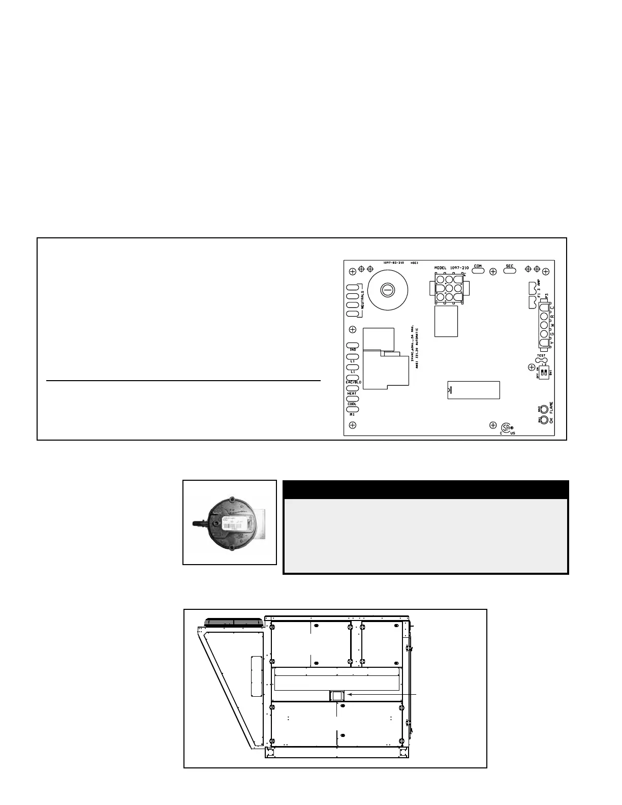
FIGURE 43B – DSI Integrated Control Module on Downstream Furnace - "D" Cabinet only
Control Status - Green LED Codes
Steady ON ......Normal Operation, No call for heat
Fast Flash ....... Normal Operation, Call for heat
1 Flash ............ System Lockout, Failed to detect or sustain ame
2 Flashes ........Pressure switch did not close within 30 seconds of
venter motor
3 Flashes ........High limit switch open
4 Flashes ........Pressure switch is closed before venter motor is
energized
Steady OFF ....Blown Fuse, No Power, or Defective Board
Flame Status - Yellow LED Codes
Steady ON ......Flame is sensed
Slow Flash ......Weak ame (current below 1.0 microamps ±50%)
Fast Flash ....... Undesired Flame (valve open and no call for heat)
9.2.3 Venting and
Combustion Air
FIGURE 45 - Heat
Section Showing
Location of Flue
Exhaust (vent) and
Combustion Air Hood
- Cabinet A, B, and C
Sizes
Tubing
Access
Control
Panel
Combustion Air Intake Panel
Compressor
Access
Gas Heat Section
Screened
Flue
(Vent)
Outlet
The gas heat section is power vented. Presence of combustion air pressure is moni-
tored by a combustion air proving switch.
2) Prepurge - The circuit board energizes the venter motor and waits for the pressure
switch to close. When the pressure switch is proven closed, the circuit board begins
the prepurge time. The ignition system circuit board runs the venter motor for a 30
second prepurge time, then proceeds to the ignition trial period.
3) Ignition Trial Period - The ignition system circuit board energizes the spark and
main gas valve. The venter remains energized. If ame is sensed at the burner during
the rst 6 seconds, the spark is de-energized. The circuit board proceeds to steady
heat.
4) Steady Heat - Circuit board inputs are continuously monitored to ensure limit and
pressure switches are closed, ame is established, and the system controller call for
heat remains. When the call for heat is removed, the ignition system circuit board de-
energizes the gas valve and begins postpurge timing.
5) Post Purge - The venter motor output remains on for a 45-second postpurge period
after the system controller is satised.
FIGURE 44 -
Combustion Air
Proving Switch
DANGER
Safe operation requires proper venting ow.
Never bypass the combustion air proving switch
or attempt to operate the heat section without
the venter running and proper ow in the vent
system. Hazardous condition could result.
9.2.3.1 Venting and
Combustion Air -
MAPS
®
Cabinets A, B,
and C
The combustion air inlet hood is located on the side of the unit near the compressor
compartment. See FIGURE 45. The ue outlet is also located on this side.

 Loading...
