Form I-MAPSIII&IV, P/N 222917R9, Page 63
9.2.3.2 Venting and
Combustion Air -
MAPS
®
III Cabinet D
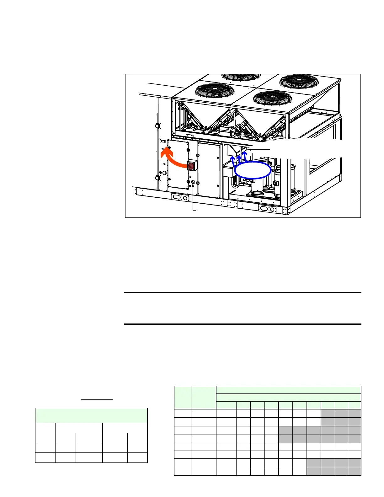
FIGURE 46 - Heat
Section Showing
Location of Flue
Exhaust (vent) and
Combustion Air Hood -
Cabinet D Sizes
Heat
Section
Door
Gas Entrance
Combustion
Airflow
Combustion Air Inlet Hood
Vent
NOTE: The illustration
shows only one furnace.
The combustion air hood is
in the same location when
the heat section has two
furnaces. Each furnace has
a vent.
On a D Cabinet, a screened vent cover was attached to each vent (ue exhaust) in
Paragraph 9.2.1.
The gas-red heat section vents combustion gas horizontally. A eld-installed vent
extension kit (P/N 221120) provides for attaching a vertical vent pipe that will allow the
vent terminal to extend above the unit. For information, contact your distributor or see
Form CP-MAPS-Vnt Ext on www.RezSpec.com.
Vent Extension Field Kit
for MAPS
®
Cabinet A, B,
or C
All gas furnaces are equipped with a temperature activated auto reset limit control. The
control is factory set at 270°F and is non-adjustable. If the setpoint is reached, the limit
control will interrupt the electric supply to the gas valves. This safety device provides
protection in the case of a lack of airow due to dirty lters or a restriction at the inlet
or outlet.
The limit control switch is mounted on the side of the heat exchanger with a capil-
lary sensor that extends across the discharge opening. The switch is accessible in
the blower cabinet of a MAPS
®
Cabinet A, B, or C system or in the heat module of a
MAPS
®
III Cabinet D system.
CAUTION: The auto reset limit control will continue to shut down
the heat section until the cause is corrected. Never bypass the
limit control; hazardous conditions could result.
9.2.4 High
Temperature Limit
Control - All MAPS
®
Cabinet Sizes
9.3 Electric Heat -
Models RECB,
REDB, RECC,
REDC
A MAPS
®
unit with an electric heat section is equipped to provide from 5 to 88 kw of
electric heat. Depending on the size, electric heat sections provide one or three stages
of heating operation or can be equipped with optional SCR modulating control.
Call for heat and staging occur in response to system controls (See Paragraph 8).
9.3.1 Electric Heat
Size
(kW)
Voltage
Electric Heaters Sequence of Operation
Stage
1 2 3 4 5 6 7 8 9 10
120 208 10 10 20 20 20 20 20
120 240 10 10 20 20 20 20 20
120 480 30 30 30 30
120 575 30 30 30 30
180 208 10 10 20 20 20 20 20 20 20 20
180 240 10 10 20 20 20 20 20 20 20 20
180 480 30 30 30 30 30 30
180 575 30 30 30 30 30 30
Electric Heat Capacity Table
- D Cabinet
Size
240/480/575V 208V
KW MBH KW MBH
120 120 410 90 307
180 180 615 135 461
Electric Heat Capacity and Sequence
of Operation - Cabinet D

 Loading...
