Form I-RDF, P/N 148384 (Rev 1), Page 21
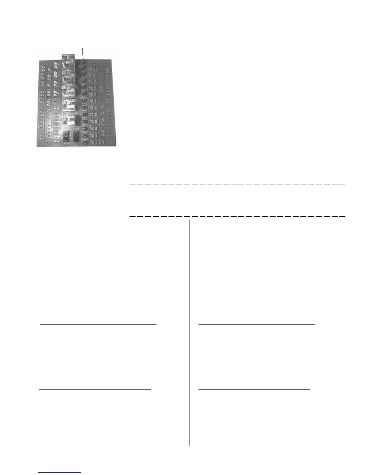
Diagnostic
Lights
oConnect a "U"-tube manometer to the main burner pressure tap.
oCheck status lights (check at each step in the Startup procedure.)
Turn ON disconnect switch.
"Circuit Control Power" light is lit.
Turn OFF disconnect switch.
oTurn the disconnect switch ON and the blower service switch to TEST
position.
"Control Switch Energized", "Starter Energized", and if equipped with
a freezestat, "Freezestat" lights are lit. After blower obtains normal
speed, check for these lights - "Outside Air Cutoff Normal"; "Low Air
Pressure Normal", "Limit Controls Normal"; "High Air Pressure
Normal"; and if equipped with options; "Low Gas Pressure Normal";
and/or "High Gas Pressure Normal".
oCheck for blower rotation. If the blower is turning backwards (see rotation
arrows), do the following:
Turn the disconnect switch OFF
Single-phase units -- rewire motor per instructions on motor wiring plate
Three-phase units -- interchange any two motor leads at the motor
contactor or starter
Turn disconnect switch ON and verify rotation.
2. Measure burner differential air pressure on the slope gauge installed in
Preparation Step 1. With the blower operating, differential air should read
between -.25" and -.75" w.c. If the slope gauge reading is not within the
limits of these numbers, do one of the following:
If the slope gauge reading is greater than -.25" (such as -.10"
w.c.), adjust the drive to increase the blower speed.
(1) Turn disconnect switch OFF.
(2) ¡ If equipped with a discharge damper, remove opposite side
blower door panel.
Turn disconnect switch ON.
Check that discharge damper is full open by loosening or
tightening the linkage.
Turn disconnect switch OFF.
Replace door panel.
Turn disconnect switch ON and recheck slope gauge.
Turn disconnect switch OFF.
(3) If reading is still greater than -.25" w.c., adjust drive to increase
fan RPM.
For systems with smaller than 7-1/2 HP motor
(a) Loosen belt tension and remove belt.
(b) Loosen the setscrew on the side of the pulley away from
the motor.
(c) Turn adjustable half of the pulley inward to increase
blower speed. One turn of the pulley will change speed 8 to
10%.
(d) Tighten the setscrew on the flat portion of the pulley
shaft.
For systems with 7-1/2 HP and larger motor
(a) Slack off all belt tension by moving the motor toward
driven shaft until the belts are free of grooves. For easiest
adjustment, remove the belts from the grooves.
(b) On the outer locking ring, locate the two locking screws
that are directly across from each other. Loosen, but do not
remove, those two screws. Do not loosen any other screws.
(c) Adjust sheave to desired pitch diameter by turning the
outer locking ring. One complete turn of the outer locking
If the slope gauge reading is less than -.75" (such as -1.0" w.c.),
adjust the drive to decrease the blower speed.
(1) Turn disconnect switch OFF.
(2) ¡ If equipped with a discharge damper, remove opposite side
blower door panel.
Turn disconnect switch ON.
Check that discharge damper is full open by loosening or
tightening the linkage.
Turn disconnect switch OFF.
Replace door panel.
Turn disconnect switch ON and recheck slope gauge.
Turn disconnect switch OFF.
(3) If reading is still less than -.75" w.c., adjust drive to decrease
fan RPM.
For systems with smaller than 7-1/2 HP motor
(a) Loosen belt tension and remove the belt.
(b) Loosen the setscrew on the side of the pulley away from
the motor.
(c) Turn the adjustable half of the pulley outward to de-
crease blower speed. One turn of the pulley will change
speed 8% to 10%.
(d) Tighten the setscrew on the flat portion of the pulley
shaft.
For systems with 7-1/2 HP and larger motor
(a) Slack off all belt tension by moving the motor toward
driven shaft until the belts are free of grooves. For easiest
adjustment, remove the belts from the grooves.
(b) On the outer locking ring, locate the two locking screws
that are directly across from each other. Loosen, but do not
remove, those two screws. Do not loosen any other screws.
(c) Adjust sheave to desired pitch diameter by turning the
outer locking ring. One complete turn of the outer locking
 Loading...