Page 26
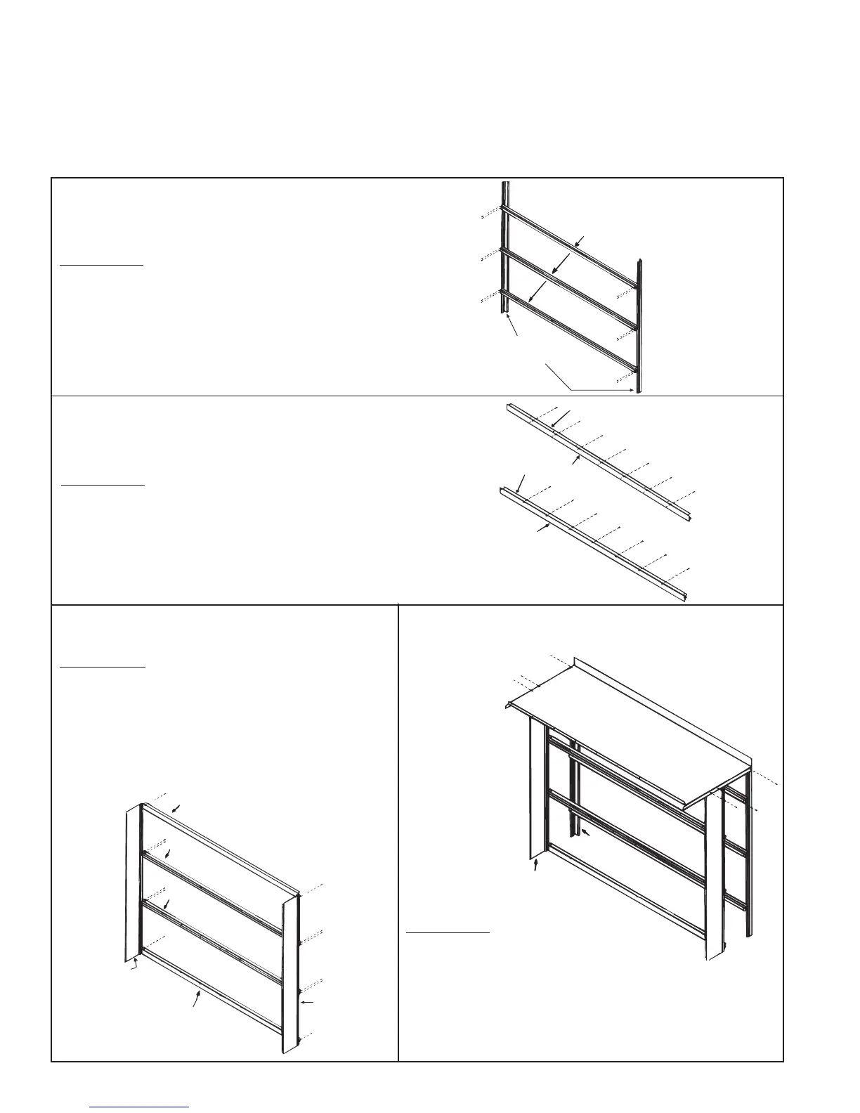
Step 1A - Assemble Inner Side of Filter Rack
(Applies to Options AS6 and AS7 only; for Option
AS2 without filters, proceed to Step 1D)
Parts Required -- Right corner post, left corner post, three of the five
pre-assembled center filter channels, and twelve 1/2" long screws
Corner posts come with two sets of holes.
For 1" filters (Option AS6), attach the three filter channel assemblies
using the holes in the corner posts closest to the inside.
For 2" filters (Option AS7), attach the three filter channel assemblies
using the holes in the corner posts closest to the outside edge.
Pre-assembled Center Filter Channels
(NOTE: There are five center filter channel
The other two are used on the other side of
the filter rack in Step 1C.)
P/N 91579
Corner Post
Top Filter channel
Bottom Filter
Channel Top Blockoff
Plate
Bottom Blockoff
Plate
Step 1 B - Sub-assemble Top
and Bottom Filter Channels and
Filter Blockoff Plates (AS6 & AS7)
Parts Required - Top and bottom filter channel; top and bottom filter
blockoff plates; and 14 screws (1/2" long)
Assemble the top blockoff plate and the top filter channel being sure
the filter channel groove is on the same side as the 90° bend in the
blockoff plate but directed away from it. Use seven screws to attach
the top blockoff plate to the top filter channel. Repeat the process
with the bottom filter channel and bottom blockoff plate.
Top Filter Channel with
Blockoff Plate (assembled in 1B)
Center Channel Assy
P/N 91578
Intermediate
Cabinet Post
Bottom Filter Channel
with Blockoff Plate
(assembled in 1B)
P/N 91578
Intermediate
Cabinet Post
Center Channel Assy
Step 1C - Assemble Outer Side of Filter
Rack (Options AS6 and AS7 only)
Parts Required - Two intermediate posts; two remaining
pre-assembled center filter channels; the top and bottom
filter channel/blockoff plate assemblies form Step 1B; and
12 sheetmetal screws (1/2" long)
For 1" filters (Option AS6), attach the channel assemblies
to the holes closest to the inside of the intermediate posts.
For 2" filters (Option AS7), attach the channel assemblies
to the holes closest to the outside edge of the posts.
P/N 91575 Top of Inlet
Hood Cabinet Section
Intermediate
Post
Corner
Post
Intermediate
Post
Corner
Post
Step 1D - Attach Cabinet Section To Corner
Posts and Intermediate Posts (Options AS2,
AS6, AS7)
Field Installed Outside Air Hood or Filter Section (cont'd)
1. Screened Air Inlet Hoods with Filters (Options AS6 and AS7 for Sizes
3-180, 3-260) - Build filter racks and cabinet section; follow all Steps.
Screened Air Inlet Hood without Filters (Option AS2 for Sizes 3-180, 3-
260) - Build cabinet section; skip Steps 1A, 1B, and 1C. Start with Step 1D
ignoring filter rack illustrations.
Assembly and
Installation Instruc-
tions for Item 2 on
page 24 (cont'd)
Parts Required - Cabinet top; the two
corner cabinet posts (if inlet hood with
filters, posts will be sub-assembled to
filter channels - Step 1A) (if AS2 with
no filters, ignore illustrated filter rack); the two intermediate cabi-
net posts (if inlet hood with filters, posts will be sub-assembled to
filter channels - Step 1C); and six 1/2" long sheetmetal screws.
Attach cabinet section top to the four posts as illustrated.
 Loading...