Page 6
8. Location and
Mounting
7. Rigging
All cabinets are furnished with a curb cap and four lifting lugs for attaching
rigging. To prevent damage to the cabinet, use spreader bars with the rigging
chains.
Mounting the system is the responsibility of the installer. Verify that the sup-
porting structure has sufficient load-carrying capacity to support the weight.
NOTE: Net weights are approximate for the standard system. Optional equip-
ment is not included.
Mounting on Field-
Supplied Supports
The system is equipped with a load-bearing curb cap which forms an integral
part of the unit. The curb cap provides required clearance from combustibles.
Whether the system is being mounted directly on a surface or being placed
"up" on additional structure, the horizontal length must be supported by two
4x4 treated wooden rails. Refer to FIGURE 3 for the appropriate lengths and
spacing. When the system is placed on the rails, the curb cap "skirt" must fit
over the edge of the boards with the rails setting inside the horizontal length of
the curb cap.
If the rails are laid directly on the mounting surface, position them as shown in
FIGURE 3. Set the system on the rails leaving the "ends" underneath open for
ventilation.
If the wooden rails are not placed directly on a surface, cross-supports should
be placed underneath the rails at the ends and at the cabinet "joint". Refer to
FIGURE 4.
IMPORTANT NOTE: Mount an outdoor unit with a minimum of 14" clear-
ance from the bottom of the inlet air hood to the mounting surface.
Depending on the building and its use, determine whether or not additional
measures should be taken to reduce the effect of blower vibration and/or noise.
When selecting a location for an outdoor installation, position the unit so that
the air inlet will NOT be facing into the prevailing wind. A minimum of 14"
(356mm) clearance is required from the bottom of the air inlet hood to the
mounting surface.
Prior to installation, be sure that the method of support is in agreement with all
local building codes. For both indoor and outdoor installations, check for ser-
vice platform requirements. If an outdoor system is being installed with bot-
tom discharge and/or return air, a full perimeter roof curb is recommended.
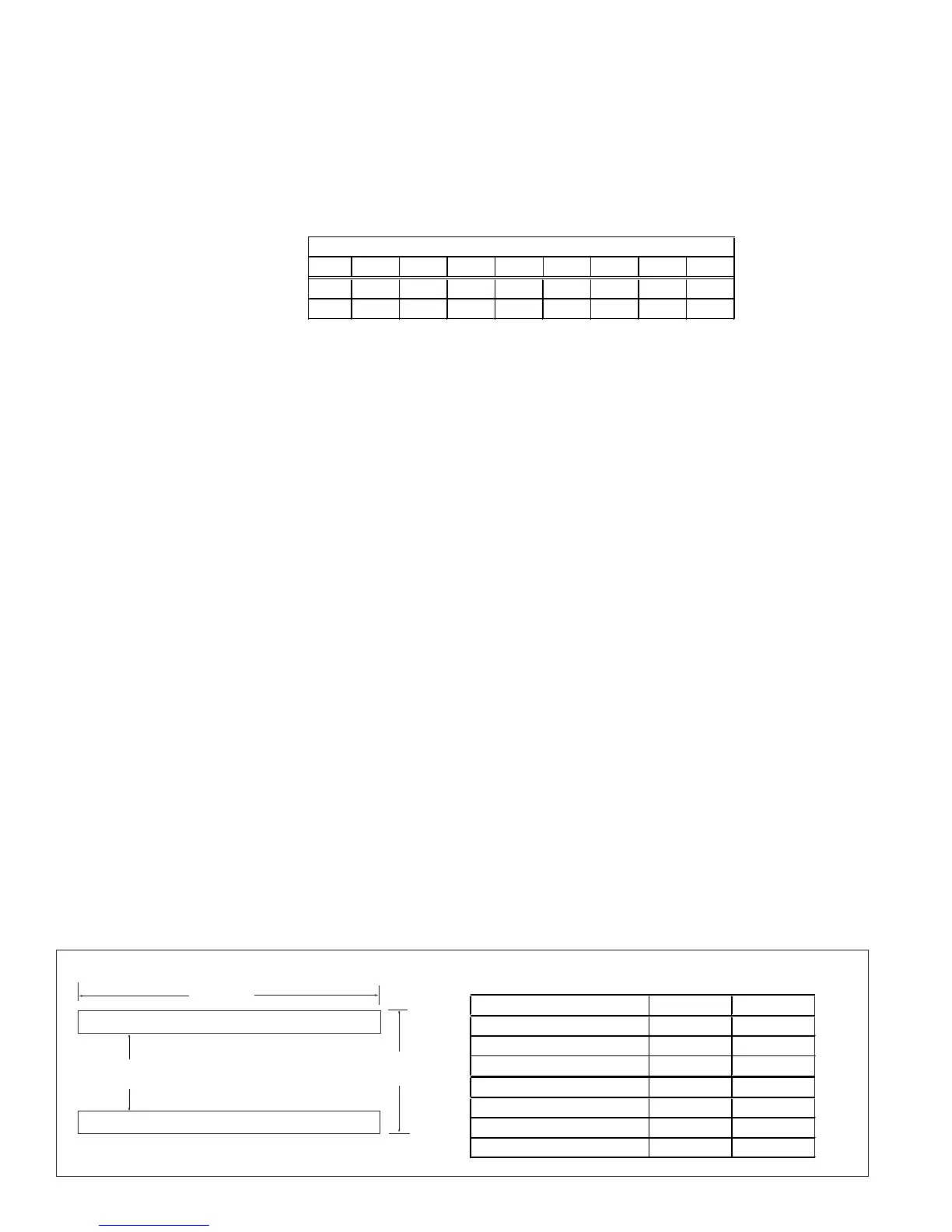
FIGURE 3 - Placement of
Mounting Rails
A
B
4 x 4 Treated Lumber
Weights
Net Wei
ht of Basic S
stem
Sizes
1-20 1-40 1-50 1-65 2-80 2-120 3-180 3-260
lbs 915 925 935 950 1455 1505 2410 2480
kg 415 420 424 431 670 683 1093 1125
Mounting Rail Placement
Model A (inches) B (inches)
1-20, 1-40, 1-50, 1-65
85-1/4 45-1/2
2-80, 2-120
85-1/4 69-7/16
3-180, 3-260, 122, 130
132-5/8 83-1/16
Model A (mm) B (mm)
1-20, 1-40, 1-50, 1-65 2165 1156
2-80, 2-120 2165 1764
3-180, 3-260 3369 2110
 Loading...