Do you have a question about the RFS APD22-D and is the answer not in the manual?
Ensures proper purging of the distribution system before dehydrator installation to prevent moisture issues.
Highlights the importance of avoiding flow restrictions in the distribution system for optimal unit performance.
Specifies requirements for placing the dehydrator, including surface type and clearance for heat dissipation.
A step-by-step guide for connecting, energizing, and verifying the dehydrator's initial operation.
Addresses common issues encountered during installation, providing symptoms and possible solutions.
Overview of the automatic dehydration process, dew point importance, and environmental factors affecting performance.
Explains the unit's automatic cycle, pressure monitoring, duty cycle, and system purge valve functionality.
Guidance on selecting the correct dehydrator model based on site conditions, power, and system requirements.
Details optional features like High Pressure, Humidity, Run Time alarms, and System Purge configurations.
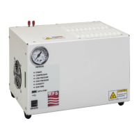
Description of the front panel pressure gauge and its indication of output pressure.
Explanation of the function of LED indicators (POWER, COMPRESSOR, alarms) on the unit's front panel.
Details the USB port's capabilities for logging, option updates, and software upgrades.
Information on the circuit breaker location and procedure for resetting after an overload.
Specifies the AC power input connector and cord requirements for different APD-D models.
Instructions for connecting the 3/8" tubing to the dry air output fitting.
Explains the function of the case fan for cooling and the necessary clearance for airflow.
Description of the alarm port for remote monitoring of configured alarms using Form C relays.
Details the screw-terminal alarm connector for wiring connections to the alarm port.
Procedure for safely disconnecting and opening the dehydrator unit to access internal components.
Instructions for accessing, inspecting, and replacing the compressor's input air filter element.
Steps for replacing the Real-Time Clock battery and resetting the unit's date and time.
Procedure for reconnecting the fan, reattaching the lid, securing it, and verifying normal operation.
Details the steps for upgrading software, configuration, or options via the USB DATA PORT.
| Brand | RFS |
|---|---|
| Model | APD22-D |
| Category | Industrial Electrical |
| Language | English |