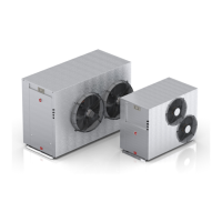
Commercial Air to Water Heat Pump Water Heater
35
TANK SENSOR INSTALLATION
Connect one of the supplied temperature sensors to the
connection terminal on the heat pump marked “Tank Sen-
sor”.
• Run out the sensor to the nearest storage tank.
• Insert a Thermostat Well (not supplied) into the tank.
• Insert the sensor all the way into the thermostat well
and secure it to the storage tank to prevent the sensor
dislodging from the well.
• Cable tie the sensor lead, curling up and tying off any
excess lead.
BUILDING FLOW TEMPERATURE
SENSOR INSTALLATION
• Connect the 2nd temperature sensor to the connec-
tion terminal on the heat pump marked “Building Flow
Sensor”.
• Run out the sensor to the building flow pipe.
• Fit a thermostat well (not supplied) in the pipe ensur-
ing the end of the sensor is in the flow of water. To
prevent the sensor dislodging from the well, secure
the sensor to the insulation using a cable tie. Alter-
natively, clamp the sensor to the outside of the pipe
using a pipe clamp prior to the insulation being fitted.
NOTE: For multiple heat pump installation, the pre-
ferred method is to interconnect the heat pumps (up to
4 maximum) via LAN cables, available as an accessory
(part number: 17534).
In this case, only one tank sensor and building flow tem-
perature sensor is required, which are connected to the
heat pump designated as the Primary.
Alternatively, each heat pump can operate independently
in which case each tank sensor and building flow temper-
ature sensor must be connected and fitted as described
above.
LOW AMBIENT BOOST
If auxiliary boosting is required for low ambient operation,
the booster should be interlocked with the heat pump to
only operate under low ambient or fault conditions.
CONNECTIONS - ELECTRICAL
THERMOSTAT
WELL
 Loading...