¢
Error status output
Indoor unit type Connector
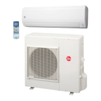
Wall mounted
RIWH07AVFJ, RIWH09AVFJ, RIWH12AVFJ,
RIWH15AVFJ
CNB02
RIWH18AVFJ, RIWH24AVFJ —
Air conditioner error status signal can be output.
Circuit diagram example
Locally purchased
Example: Display
Indoor unit
control PCB *1
Connected unit
Example:
Relay unit
1
2
Signal
Relay
power
supply
V
Connector
33 ft
(10 m) *2
DC 24 V
• *1: PCB of Communication kit is used for wall mounted (RIWH07AVFJ, RIWH09AVFJ, RI-
WH12AVFJ, and RIWH15AVFJ) type.
• *2: Make the distance from the PCB to the connected unit within 33 ft (10 m).
• Relay spec.: Max. DC 24 V, 10 mA to less than 500 mA.
On
Off
Error
Normal
Error status
Output signal
Optional part
Indoor unit type Part name Model name
Wall mounted
RIWH07AVFJ, RIWH09AVFJ,
RIWH12AVFJ, RIWH15AVFJ
External connect kit RXXWZXZ5
RIWH18AVFJ, RIWH24AVFJ — —
Indoor unit type Part name Model name
Wall mounted
RIWH07AVFJ, RIWH09AVFJ,
RIWH12AVFJ, RIWH15AVFJ
Communication kit RXXCBXZ2
RIWH18AVFJ, RIWH24AVFJ — —
*For operating the external input function, the wall mounted (RIWH07AVFJ, RIWH09AVFJ,
RIWH12AVFJ, and RIWH15AVFJ) type requires Communication kit (RXXCBXZ2) in addition
to the wire (RXXWZXZ5).
DESIGN & TECHNICAL MANUAL
- 32 -
MULTI TYPE
5 rooms type
 Loading...