- (01-14) -
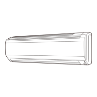
WALL MOUNTED TYPE
RIWH09-12AVFJ
WALL MOUNTED TYPE
RIWH09-12AVFJ
9. EXTERNAL INPUT & OUTPUT
Connector INPUT OUTPUT REMARKS
CNA01 Control input -
See external
input/output settings
for details.
CNB01 - Operation status output
CNB02 - Error status output
9-1. EXTERNAL INPUT
CONTROL INPUT (Operation/Stop or Forced stop)
The air conditioner can be remotely operated by means of the following on-site work.
"Operation/Stop" mode or "Forced stop" mode can be selected with function setting of indoor unit.
Unit operation is started at the following contents by adding the contact input of a commercial ON/OFF switch to a
connector on the external control PC board and turning it ON.
Unit operation Initial setting after power is ON Starting mode other than initial setting
Operation mode Auto changeover Mode at previous operation
Set temperature 75°F (24°C) Temperature at previous operation
Air ow mode AUTO Mode at previous operation
Air direction (swing) Standard air direction (swing OFF) Air direction at previous operation
z
Circuit diagram example
Signal
Locally purchased
Indoor unit
control PC board Communication kit
Optional parts
Connector
1
3
*33ft. (10m)
Connected unit
Ex.) Switch
* Make the distance from the PC board to the connected unit within 33ft. (10m).
Contact capacity: DC 24 V or more, 10 mA or more.
Use non-polar relays and switches.
z
When function setting is in "Operation/Stop" mode
Operation
Stop
ON
OFF
Input signal
Indoor unit
 Loading...