MAINTENANCE
172 08/12 Maintenance Section 5-25
© 2012 Alamo Group Inc.
MAINTENANCE
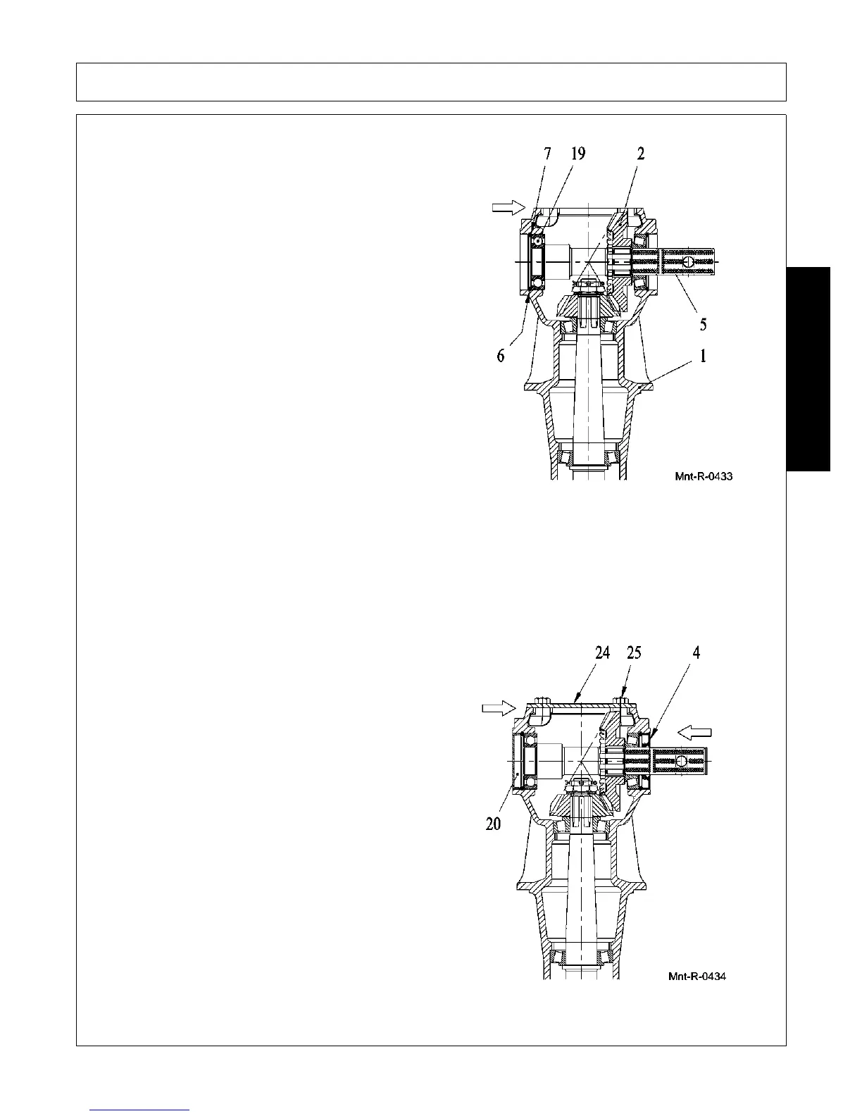
12. Assemble bearing (19) on the shaft (5), using
pipe and hammer.
13. Assemble pre-mounted shaft (5) inside
housing (1), using chisel and hammer, bearing
(19) using pipe and hammer, snap ring (6).
14. Hit the shaft (5) in order to set the axis, from
both sides, using a hammer.
15. Check the assembled axis preload (K), using a
torquemeter.
16. Disassemble snap ring (6).
17. Assemble shims (7) and snap ring (6).
18. Hit the shaft (5) in order to set the axis, from
both sides, using a hammer.
19. Check the assembled axis preload, (W), using
a torquemeter.
20. The difference between the value (W) and the
value (K) is the axis preload that must be to
1÷5 kgcm.
21. If the value is not correct disassemble the snap
ring (6) and change the shims (6) setting,
reassemble the snap ring (6) and repeat the
setting axis in order to obtain the right preload.
22. In order to test the right mesh between the gears, use a color like prussian blue on the gear’s toothing.
23. Rotate manually the shaft (5).
24. Verify the right mesh between gears, (see the technical specifications on page 12), the value must be to
0.16 ÷ 0.42 mm.
25. In order to have the correct backlash, change shims set (7), (Please be aware that when you change the
shims set you will also have to re-set the preload).
26. Assemble cap (20), oil seal (4), using pipe and
hammer.
27. Put a silicone film between contact surfaces of
the housing and cover (24) than assemble
cover (24), bolts (25) and tighten to 5÷6.4 kgm.
 Loading...