EasyManua.ls Logo

Ricoh fax180 User Manual

Ricoh fax180
128 pages
To Next Page IconTo Next Page
To Previous Page IconTo Previous Page
Page #32 background imageLoading...
Page #32 background image
4. SERVICE TABLES AND PROCEDURES
4.1. SERVICE LEVEL FUNCTIONS
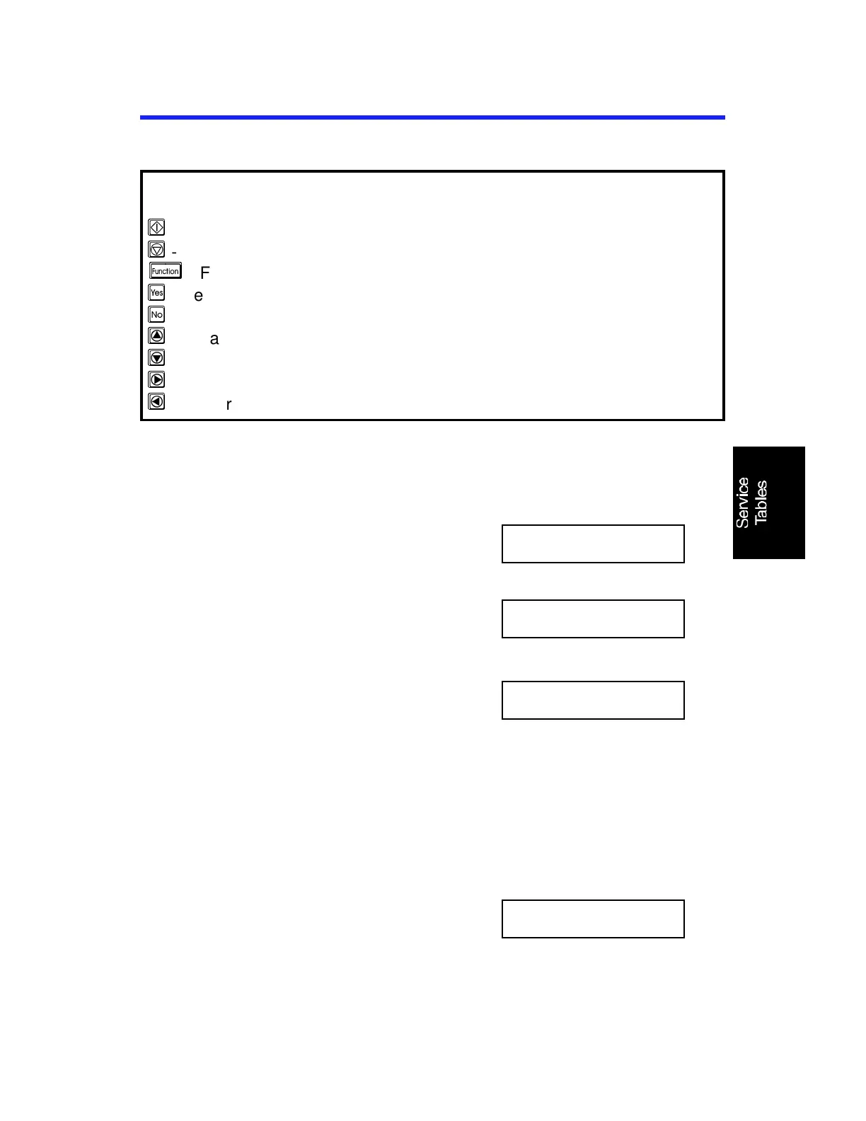
In this section, frequently used keys are referred to with the following
symbols.
S
- Start key
s
- Stop key
FU
- Function key
Y
- Yes key
N
- No key
^
- Up arrow key
_
- Down arrow key
>
- Right arrow key
<
- Left arrow key
4.1.1. Bit Switch Programming (Function 01)
1. FU 6 1 9 9 5
then immediately Y
FUNCTION KPAD/NEXT
SERVICE FUNCTIONS
2. 0 1 Y
SYS DF : 0000 0000
BITSW 00: 0000 0000
Bit 7 is displayed at the left, and bit 0 at
the right.
3. Scroll through the bit switch menu: * or
#
Example: To see the communication
switches : # × 3
Then scroll through the bit switches.
Increment bit switch: >
Decrement bit switch: <
Example: Display bit switch 3: > x 3
COM DF : 0000 0000
BITSW 00: 0000 0000
4. Adjust the bit switch.
Example: To change the value of bit 7,
press 7
COM DF : 0000 0000
BITSW 03: 1000 0000
August 7th, 1995 SERVICE TABLES AND PROCEDURES
SERVICE LEVEL FUNCTIONS
4-1

Questions and Answers:

Ricoh fax180 Specifications

General IconGeneral
Printing MethodThermal transfer
Copier FunctionYes
TypePlain paper fax
Automatic Document Feeder Capacity10 sheets
Fax Featuresautomatic redial
DisplayLCD

Summary

1. OVERALL MACHINE INFORMATION

1.1. SPECIFICATIONS

Details the technical specifications of the machine, including document size, data rates, and power requirements.

1.2. FEATURES

Lists the available features of the RICOH FAX180/170, categorized by equipment and communication capabilities.

1.3. COMPONENT LAYOUT

Identifies and describes the major mechanical, drive, and electrical components of the machine.

1.4. OVERALL MACHINE CONTROL

Explains the machine's control system, including the FCU and its component blocks.

1.5. VIDEO DATA PATH

Describes the flow of video data during transmission, reception, and copying processes.

1.6. POWER DISTRIBUTION

Illustrates how power is distributed throughout the machine, detailing PSU and FCU outputs.

2. DETAILED SECTION DESCRIPTIONS

2.1. SCANNER

Provides detailed information on the scanner component, its mechanisms, and operations.

2.2. PRINTING

Details the printer component, including its mechanisms, paper feeding, and cutter operations.

2.3. PCBs

Lists and describes the main Printed Circuit Boards (PCBs) of the machine.

3. INSTALLATION

3.1. INSTALLING THE MACHINE

Provides general instructions for installing and setting up the machine.

3.2. INITIAL PROGRAMMING

Details the initial programming steps required after installation.

4. SERVICE TABLES AND PROCEDURES

4.1. SERVICE LEVEL FUNCTIONS

Outlines various diagnostic and adjustment functions available in service level.

4.2. BIT SWITCHES

Details the system, scanner, printer, communication, and G3 switches.

4.3. NCU PARAMETERS

Provides a comprehensive list of NCU parameters and their default settings.

4.4. DEDICATED TRANSMISSION PARAMETERS

Explains how to program and configure dedicated transmission parameters.

4.5. SERVICE RAM ADDRESSES

Lists service RAM addresses for system parameters, counters, and settings.

5. REPLACEMENT AND ADJUSTMENT

5.1. EXTERIOR

Covers the replacement of external parts of the machine.

5.2. SCANNER

Details the replacement procedure for the scanner's CIS unit.

5.3. PRINTER

Details the replacement procedures for printer components like the thermal head.

5.4. PCBs

Describes the replacement of the PSU, FCU, and NCU PCBs.

5.5. ROLLERS AND MOTORS

Details the replacement procedures for rollers and motors.

6. TROUBLESHOOTING

6.1. COPY QUALITY TROUBLESHOOTING

Provides troubleshooting steps for various copy quality issues.

6.2. MECHANICAL PROBLEMS

Addresses mechanical problems related to the ADF/Scanner and Printer.

6.3. ERROR CODES

Lists and explains error codes, their meanings, and suggested actions.

Related product manuals