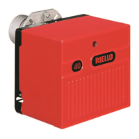
1. BURNER DESCRIPTION
One stage kerosene and light oil burner.
1. BURNER DESCRIPTION. . . . . . . . . . . . . . 1
1.1 Burner equipment . . . . . . . . . . . . . . . . . . . 2
2. TECHNICAL DATA . . . . . . . . . . . . . . . . . . 2
2.1 Technical data . . . . . . . . . . . . . . . . . . . . . . 2
2.2 Overall dimensions . . . . . . . . . . . . . . . . . . 2
2.3 Working field . . . . . . . . . . . . . . . . . . . . . . . 3
3. INSTALLATION. . . . . . . . . . . . . . . . . . . . . 3
3.1 Mounting the burner . . . . . . . . . . . . . . . . . . 3
3.2 Hydraulic systems . . . . . . . . . . . . . . . . . . . 4
3.3 Electrical wiring . . . . . . . . . . . . . . . . . . . . . 5
4. WORKING . . . . . . . . . . . . . . . . . . . . . . . . 6
4.1 Combustion adjustment. . . . . . . . . . . . . . . 6
4.2 Nozzles recommended . . . . . . . . . . . . . . . 6
4.3 Pump pressure . . . . . . . . . . . . . . . . . . . . . 6
4.4 Electrodes setting . . . . . . . . . . . . . . . . . . . 6
4.5 Air damper adjustment . . . . . . . . . . . . . . . 7
4.6 Burner start-up cycle . . . . . . . . . . . . . . . . . 7
5. MAINTENANCE . . . . . . . . . . . . . . . . . . . . 8
5.1 Maintenance position . . . . . . . . . . . . . . . . 8
6. FAULTS / SOLUTIONS . . . . . . . . . . . . . . 9
O
Burner with CE marking in conformity with EEC Directives: Electromagnetic Compatibility 2004/108/EC, Low
Voltage 2006/95/EC, Machines 2006/42/EC and Efficiency 92/42/EEC.
O
CE Certification No.: 0036 0315/01 as 92/42/EEC.
O
The burner meets protection level of IP 40, EN 60529.
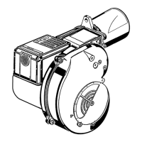
1 – Return line
2 – Suction line
3 – Gauge connection
4 – Pump pressure regulator
5 – Vacuum gauge connection
6 – Screws fixing air damper
7 – Hydraulic jack with air damper
8 – Reset button with lock-out lamp
9 – Flange with insulating gasket
10 – Control box
5
D5506
Fig. 1
1
2
3
4
8
6
6
7
9
10
HYDRAULIC JACK OPERATION 7)(Fig. 1)
It is strongly recommended a periodic check of
the pump pressure operation (annually or bet-
ter every six months, if the burner operation is
continuous).
If the value is lower than 1 bar, compared to
that one of the initial setting, please check the
cleaning of the pump and line filters.
In case the pressure setting was not restora-
ble, please replace the pump, in order to guar-
antee that the pump pressure during the pre-
purge time is at least 3.7 bar.

 Loading...