1. BURNER DESCRIPTION. . . . . . . . . . . . 1
1.1 Burner equipment . . . . . . . . . . . . . . . . . 1
2. TECHNICAL DATA . . . . . . . . . . . . . . . . . 2
2.1 Technical data . . . . . . . . . . . . . . . . . . . . 2
2.2 Accessories . . . . . . . . . . . . . . . . . . . . . . 2
2.3 Overall dimensions . . . . . . . . . . . . . . . . 3
2.4 Firing rate . . . . . . . . . . . . . . . . . . . . . . . . 3
3. INSTALLATION. . . . . . . . . . . . . . . . . . . . 4
3.1 Heat generator fixing . . . . . . . . . . . . . . . 4
3.2 Working position . . . . . . . . . . . . . . . . . . 4
3.3 Fuel supply . . . . . . . . . . . . . . . . . . . . . . 5
3.4 Hydraulic systems . . . . . . . . . . . . . . . . . 5
3.5 Electrical wiring . . . . . . . . . . . . . . . . . . . 7
4. WORKING . . . . . . . . . . . . . . . . . . . . . . . 8
4.1 Combustion adjustment. . . . . . . . . . . . . . 8
4.2 Recommended nozzles. . . . . . . . . . . . . . 8
4.3 Electrodes adjustment. . . . . . . . . . . . . . . 9
4.4 Pump pressure . . . . . . . . . . . . . . . . . . . . 9
4.5 Combustion head setting. . . . . . . . . . . . . 9
4.6 Air damper adjustment . . . . . . . . . . . . . . 9
4.7 Burner start-up cycle. . . . . . . . . . . . . . . . 10
5. MAINTENANCE . . . . . . . . . . . . . . . . . . . 10
6. FAULTS / SOLUTIONS . . . . . . . . . . . . . 11
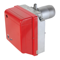
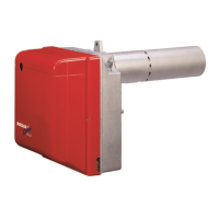
1. BURNER DESCRIPTION
One stage light oil burner.
If the burner is to be combined with a hot air generator in Germany (WLE according to DIN 4794), the con-
trol box must be replaced with a Riello 550 SMD control box (remove the bridge), and the flame sensor
must be replaced with the amplified type (both fully interchangeable). This control box, combined with the
“remote reset kit” (which can be ordered separately), means that the burner can be reset by remote control.
1 – Oil pump
2 – Control-box
3 – Reset button with lock-out
lamp
4 – Flange with insulating
gasket
5 – Air damper adjustment assembly
6 – Nozzle holder assembly
7 – Sensor llama
Fig. 1
S7179
. . . . . . . . . . . . . . . . . . . No. 2
 Loading...