SECURITY COMBINED PIR +
GLASS BREAK DETECTOR
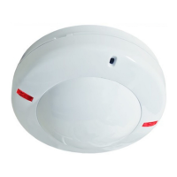
«ORLAN-2»
Installation Guide
1 General Information
Security combined PIR + glass break ceiling-mounting detector
«Orlan-2» (hereinafter, the Detector) has the following two independent
detection channels:
- Glass break channel (hereinafter, GB channel);
- Passive infrared channel (hereinafter, PIR channel).
GB channel is intended for detecting destruction of plate glass.
PIR channel is assigned for detecting intrusaion into protected area
of closed premises.
The Detector generates an alarm message by output relay contacts
opening.
2 Features
Table 1
Parameter Value
PIR channel detection zone diameter at
mounting height of 5 m, not less
9 m
Minimum controlled glass area, not less 0,1 m
2
0,05 m
2
PIR channel detected speed range 0,3...3 m/s
Power supply, V DC 9...15 V
Maximal current, commutated by executive
relay contacts at maximal voltage 72 V
30 mА
Warm-up time after energizing, not more 60 s
Operating temperature
From minus 20 to
+45 °С
PIR channel detection angle in horisontal
plane
360°
GB detection angle:
- horisontal
- vertical
120
0
90
0
IP rating IP30
Relative humidity without moisture conden-
sation
95% at 25 °С
Current consumption, maximum 35 mА
Dimensions (diameter х height), not more 105 х 48 mm
Weight, not more 100 g
Average service life 8 years
3 Choosing the Installation Place
When choosing the Detector installation place, it is advisable to
take note of the fact that the detection zone may be limited by non-
transparent objects (curtains, houseplants, cabinets, bookcases, etc.),
as well as by glass and mesh partitions. There must be no windows, air
conditioners, space heaters or heating radiators in the PIR detection
zone. Maximal installation height is 5 m. Distance between the Detector
and the farthest point of the monitored glass should not exceed 6
m. The Detector microphone should be oriented strictly towards the
protected surface of a glass construction. The Detector wires should
be laid far enough from power supply cables.
PIR channel detection zone pattern is shown in Figure 1.
Figure 1 – PIR channel detection zone pattern
Figure 2 – GB channel detection zone pattern
Side view
Microphone orientationMicrophone orientation
Top view
R 6 м
90
0
R 6 м
120
0
100 г
105 х 48 мм
95% при 25 °С
от минус 20 до плюс 45 °С
объемная конусообразная.
10 дальних зон, 1 средняя,
1 ближняя
9 м
35 мА
6 м
0,1 м
2
3 м
360
0
120
0
90
0
0,05 м
2
· put off the printed circuit board (PCB) by unfastening the latch,
located on the base;
· Drill the holes in the base (See Figure 3) for the Detector wiring
and fastening the base;
· Choose the place of installation, mark the places for mounting
holes with regard to the openings on the detector base, drill holes in
the place of installation;
· Pass the wire through the mounting holes in the base, leaving
several centimeters of installation wire for its fastening to the socket
inside the case;
· Fix the base of the detector on the chosen place
· set down PCB and microphone on their places.
4 Installation of the Detector
· Put off the Detector cover by its turning counter-clockwise until
tight (See Figure 3);
Figure 3 – Base and cover of the Detector
Base
Cover
Holes for wiring
Slot
Latch
Holes for a base
fastening
Microphone mounting
seat
10 m
5 m
9 m
5 Connection
Fulfill connections in accordance with Figure 4.
Figure 4 – The Detector connection pattern
To CP «Alarm»
via GB channel
+12V- FAILURE GB Loop PIR Loop
To CP «Alarm»
via PIR channel
To control panel (CP)
«Tamper or failure
message»
To power
supply unit
- Set operation mode by means of DIP-switches in accordance with
particular application conditions (DIP-switches assignment is listed in
the Table 2);
- Install the Detector cover on its place.
Table 2
DIP-switch Position
Mode
DIP-switch
ON OFF
GB sensitivity «1» max - 6 dB
GB sensitivity «2» max -12 dB
Installation height «3» 5 m 2,5 m
Alarm memory «4» ON OFF
Indication «5» ON OFF
Test mode «6» ON
OFF
(standby mode)