Programmable Relay ● User Manual for ELC, EXM and PR Series 126 2020 v6.0 ● © Rievtech Co.,
Ltd. ● www.rievtech.com
Using this method, you will obtain a virtual hysteresis and
reduce the input response to short signals.
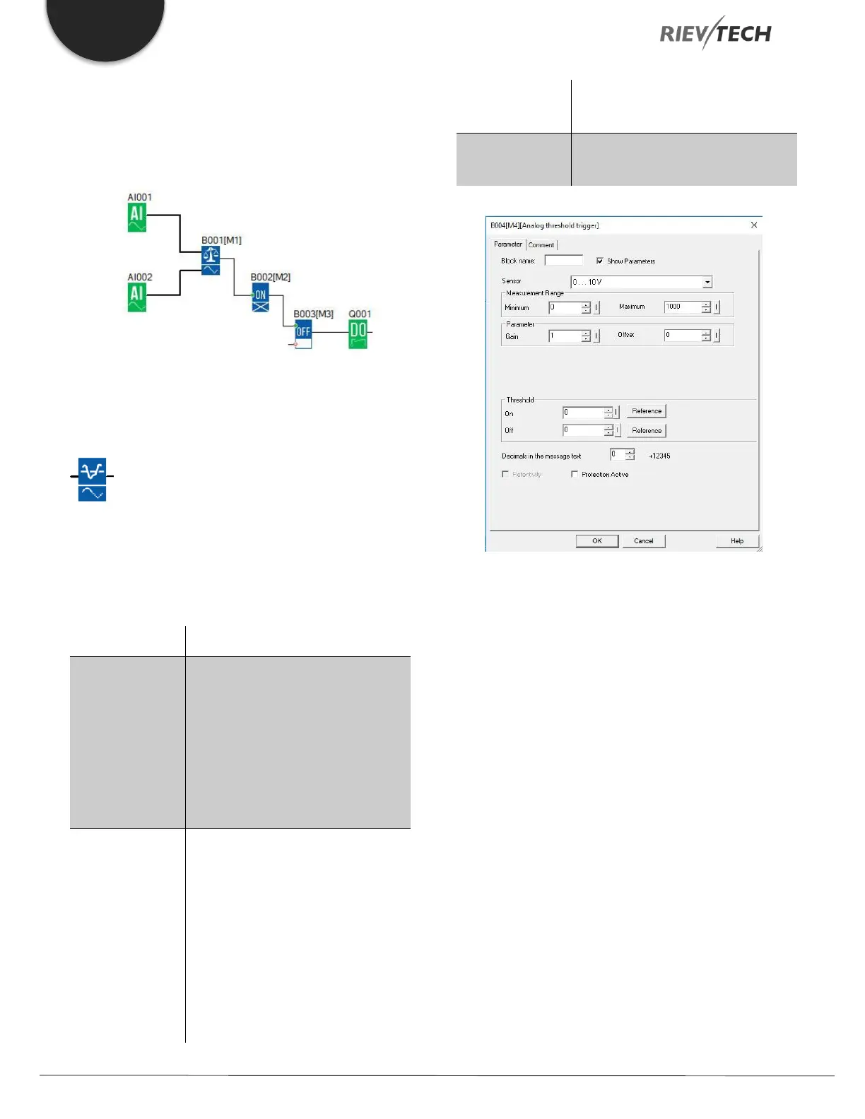
Function block diagram
Analogue Threshold Trigger
Description of function
The output is set or reset depending on two configurable
thresholds (hysteresis).
Input the analogue signal to be
evaluated at input Ax.
Use the analogue inputs AI1...AI8,
the analogue outputs AQ1 and
AQ2.
0 - 10 V is proportional to 0 - 1000
(internal value).
A: Gain
Range of values: ± 10.00
B: Zero offset
The range of values: ± 10,000
On: On threshold
The range of values: ±20,000
Off: Off threshold
The range of values: ± 20,000
p: Number of decimals
Range of values: 0, 1, 2, 3
Q is set or reset depending on the
set thresholds.
Parameter On and Off
The On and Off parameters can be provided by the actual
value of another already-programmed function:
Analog comparator (Ax – Ay) Analog threshold trigger
(Ax)
Analog amplifier (Ax) Analog multiplexer (AQ)
Analog ramp (AQ) Mathematic instruction
(AQ)
PI controller (AQ) Up/down counter (Cnt)
Analog filter (AQ) Average value (AQ)
Max/Min (AQ) On-delay (Ta)
Off-delay (Ta) On-/off-delay (Ta)
Retentive on-delay (Ta) Wiping relay(pulse output)
(Ta)
 Loading...


