Programmable Relay ● User Manual for ELC, EXM and PR Series 152 2020 v6.0 ● © Rievtech Co.,
Ltd. ● www.rievtech.com
Description of the function
The latching relay represents a simple binary memory
logic. The output value depends on the input states and
the previous status at the output.
Logic table of the latching relay:
When retentivity is enabled, the output signal corresponds
to the signal status prior to the power failure.
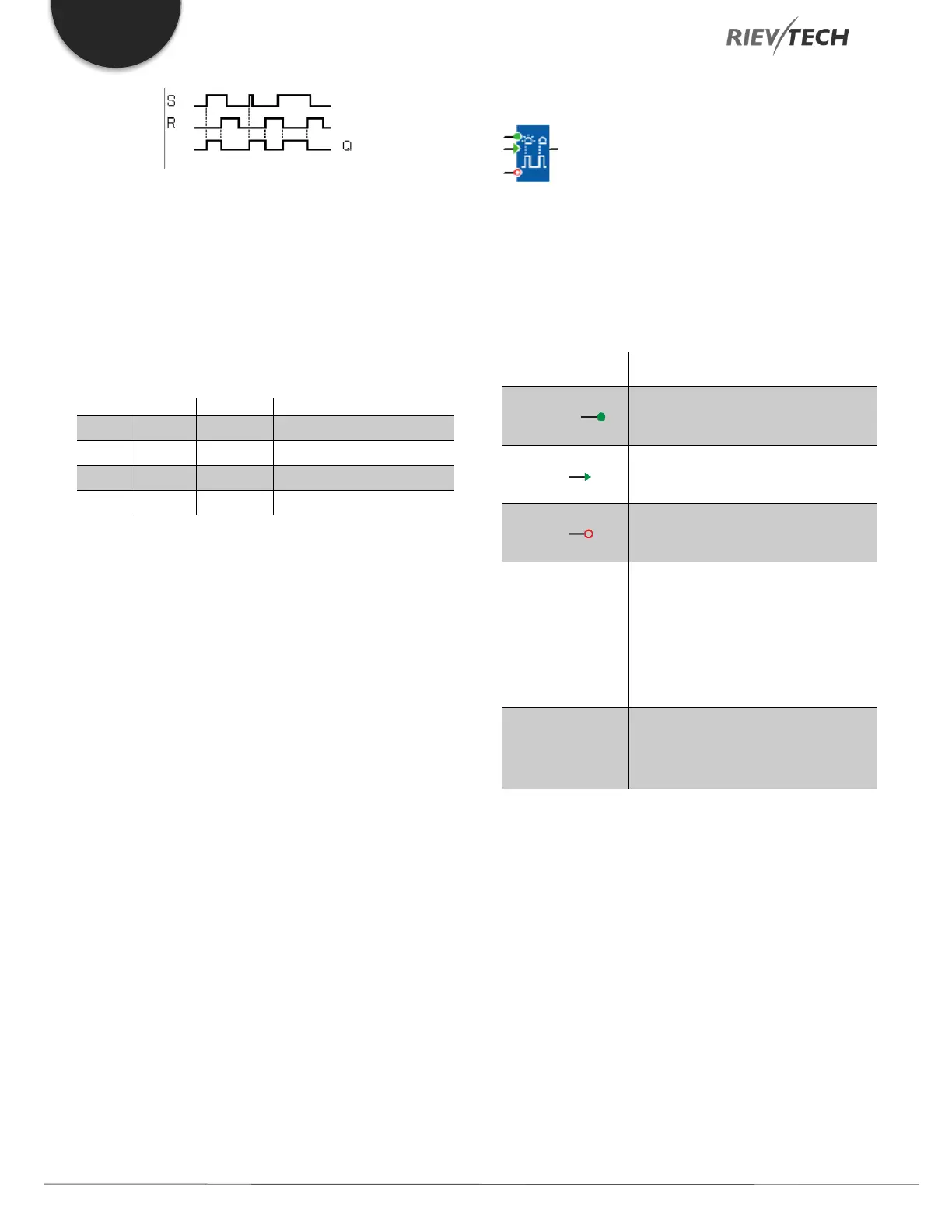
Pulse Relay
Description of function
The output is set and reset with a short one-shot at the
inputs S and R respectively.
You switch output Q on or off with a
signal at input Trg (Trigger) input.
A one-shot at input S (Set) sets the
output to logical 1.
A one-shot at input R (Reset) resets
the output to logical 0
Selection:
RS (input R priority), or
SR (input S priority)
Retentivity set (on) = the status is
retentive in memory.
Q is switched on with a signal at
Trg and is reset again at the next
Trg pulse if both S and R = 0.