VD Block
Description of Function
This function provides for storing 32-bits of data, four
characters using the Decimal value of each character,
which can be used in MQTT communications.
A maximum of 509 VD blocks can be used per xLogic PLC
program and the number is reduced with every occurrence
of VB or VW blocks used.
This block can be used by the Subscribe MQTT function
to determine the start character position of a string to be
received.
Example:
Figure 58 - VD Block Start Address
Any characters received by the above block will be stored
starting in block VD20. The maximum number of
characters allowed is 256.
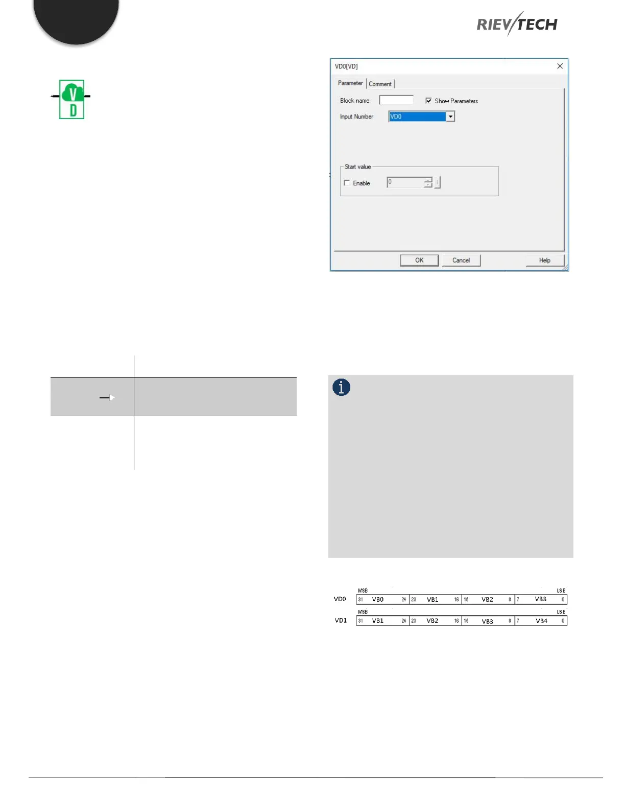
NOTICE:
VD Blocks use the same memory area as VB and
VW blocks, so care must be taken if both types of blocks
are used in the same program. In the example below,
VD1 has VB1 as its most significant byte and VB4 as its
least. You can use VD blocks as a kind of pointer, where
VDx will have VBx as its most significant byte. For
example, is you used VD53 as the input number setting,
then the most significant byte would be VB53, followed
by VB54, VB55 and least significant byte would be VB56.
Figure 59 - VD Block Memory
 Loading...


