6
Rinnai Corporation Hydronic Air Handler Manual
LOCATING AND MOUNTING THE HYDRONIC AIR
HANDLER
General
The multi-position 37AHA Series Hydronic Air
Handlers are shipped in packaged configuration. This
means that the units may be installed without
assembly and/or modifications when configured for
bottom return air inlet application; however, some
modifications and assembly are necessary if units are
to be installed in an application that requires side
return air inlet arrangement. For instructions on
required modifications and assembly refer to Figures 3
and 4.
Installation
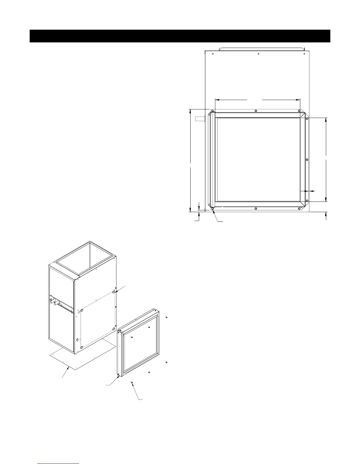
Figure 3: Modification of Unit to Accommodate
Side Filter Rack Installation
USE EXISTING SCREW HOLE
TO LOCATE FILTER RACK
17 3/4"
23/16"
1/8"
21 11/16"
3/8"
17 15/16"
Figure 4: Side Filter Rack Installation
NOTE: For side return application, obtain Side Filter
Rack” and “Bottom Fill Plate from your area
authorized Rinnai® distributor.
INSTALL RETURN BLANK OFF
PLATE (BOTTOM FILL PLATE)
AHA045: P/N 603000011
AHA060: P/N 603000012
AHA075: P/N 603000013
AHA090: P/N 603000014
SIDE FILTER
RACK ASSEMBLY
P/N 603000015
SHARED UNIT SCREW
USE TO LOCATE
FILTERASSEMBLY
CUT SIDE RETURN OPENING
IN UNIT USING THE (4)
LOCATING KOCKOUTS
 Loading...