KBD Series Manual 33
Locate the vent and intake air terminaon using the
following guidelines:
1. For installaons with mulple Tankless Water Heaters,
refer to Figure 16 for proper exhaust and combuson
air piping placement.
2. Roof penetraon of the vent and intake air piping
should be such that the combuson air intake is a
minimum 12” (30.5 cm) from the adjacent vent pipe of
the other water heater. For installaons in the U.S.
refer to Figure 16. For installaons in Canada, refer to
clearances required by CAN/CSA B149.1.
-
Locate the vent and intake air terminaon using the
following guidelines:
1. The total length of the vent or intake air piping must
not exceed the limits given in maximum equivalent
vent length tables. The equivalent length for 90° el-
bows and terminaon associated with the respecve
vent and intake air piping arrangement MUST be
subtracted from total length listed in maximum
equivalent vent length tables.
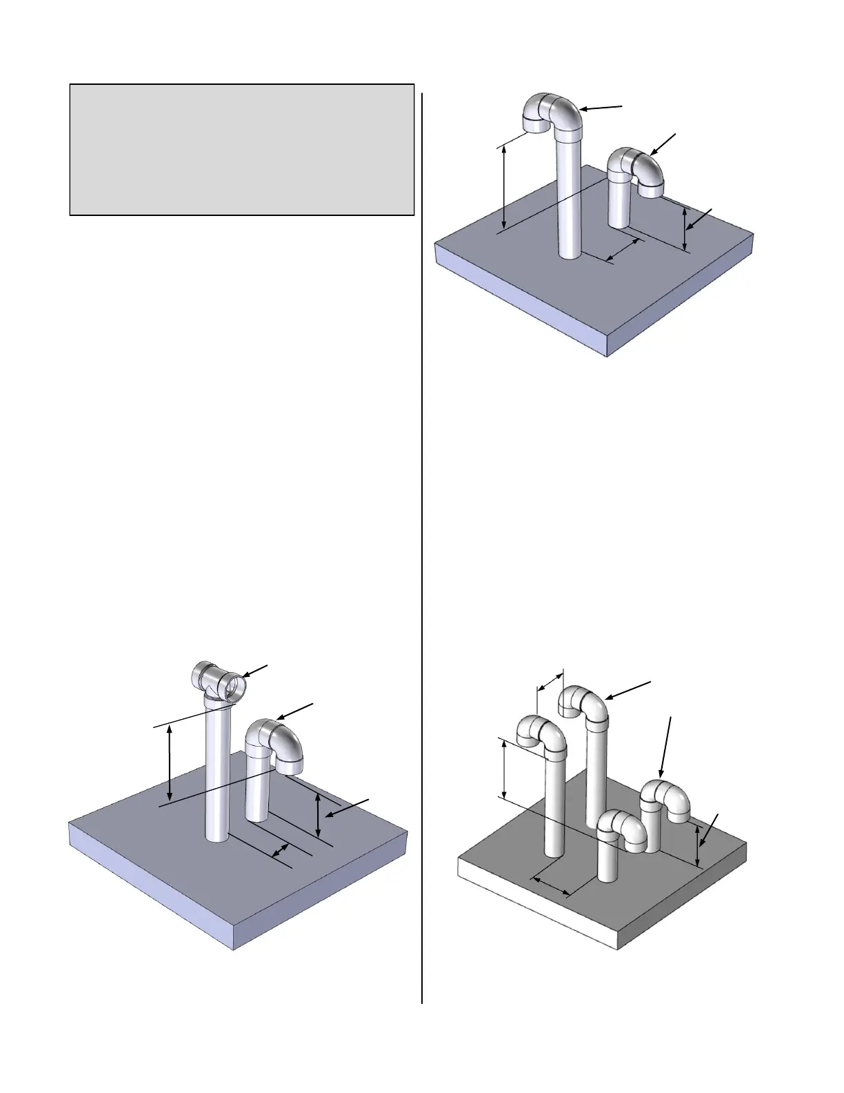
2. For roof terminaons installed as shown in gure to the
right, the intake air piping must terminate using a tee
or combinaon of elbows. The terminaon must be
installed 12” (30.5 cm) above roof or the highest
ancipated snow level.
3. The vent must terminate vercally with a coupling to
facilitate the bird screen and must be located 12” (30.5
cm) minimum above the combuson air inlet.
4. The vent and intake air terminaons must be
located a radial distance of 12” minimum (30.5 cm)
from outer wall of vent terminaon to outer wall of
combuson air intake terminaon.
-
Cered PVC/CPVC Vent Terminaon Opons (connued)
All gures shown in this secon is in reference to at roofs.
For heights of venng passing through a pitched roof, refer
to NFPA 54/ANSI Z223.1-09 (table and gure 12.7.2), CSA
B149.1-10 (gure 8.1) Pitched Roof Terminaon Clearances
Diagram (this manual)
12” min
above air
intake
opening
12” min
12” above
grade or
ancipated
snow level
Vent Terminaon
Combuson air terminaon
12” min
above air
intake
opening
12” above
grade or
ancipated
snow level
Vent Terminaon
Combuson air terminaon
12” min
12” min
12” min
above air
intake
opening
12” above
grade or
ancipated
snow level
Combuson Air Terminaon
Exhaust Vent Terminaon
12” min
 Loading...