ON: A cada 65 minutos
OFF*: A cada 15 minutos
4. Usado para determinar o interruptor de lingüeta interno.
ON: Desabilitado
OFF*: Habilitado
5. Usado para determinar o modo de contato.
ON: Normalmente Fechado (NC)
OFF*: Normalmente Aberto (NO)
6. Usado para determinar o tempo de resposta.
ON: Slow-500 ms (Para operação com contatos magnéticos,etc.)
OFF*: Fast-10 ms (Para operação com sensores de impacto)
7. Usado para determinar o status HOLD do transmissor.
ON: Haverá um intervalo de 2.5 minutos entre as transmissões de detecção de alarme. (As
mensagens de restauração serão enviadas imediatamente).
Nota: Apenas uma mensagem de alarme é transmitida durante um intervalo de 2.5 minutos.
OFF*: Não há intervalo entre as detecções de alarme (a unidade transmite depois de cada detecção).
Nota: Em ambos status HOLD ocorre o seguinte:
1. Ao desconectar o terminal de entrada o detector envia um alarme depois de 500ms.
2. Ao reabrir e fechar as entradas, o detector cria um alarme, e uma restauração extra.
8. Não aplicável
5. REMOÇÃO DA TAMPA DIANTEIRA (Figura 1).
6. ESTABELECENDO A COMUNICAÇÃO TRANSMISSOR / RECEPTOR
O T72 deve identificar-se ao receptor do sistema gravando sua mensagem codificada na
memória de endereços do receptor. Este procedimento é realizado da seguinte maneira:
a. Coloque o receptor no Modo Write
b. Remova o material isolante da pilha (Fig. 2).
Mande uma mensagem Write pressionando os dois botões do tamper (dianteiro e traseiro) pelo
menos por 3 segundos. Verifique se o T72 foi identificado pelo receptor.
c. Coloque o receptor no Modo Normal.
Nota: se por algum motivo é necessário retransmitir uma mensagem Write, pressione os dois
botões do tamper (posterior e dianteiro) pelo menos por 3 segundos.
7. SELEÇÃO DO LOCAL DE INSTALAÇÃO
a. Escolha um local adequado para conseguir uma alta qualidade de comunicação, e perto do
detector com fio (contato seco).
Coloque o aparelho na máxima altura possível.
b. Fixe temporariamente o aparelho neste ponto usando fita adesiva de dupla face.
c. Envie um sinal de Alarme (abrindo ou fechando momentaneamente as terminais de entrada) e
verifique se o receptor recebeu o sinal. Caso o sinal de alarme não tenha sido detectado,
reposicione o T72 e tente novamente
8. MONTAGEM FINAL
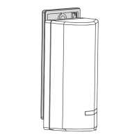
Separe a parte traseira do transmissor (Fig. 3), e coloque todas as partes em seus respectivos
lugares (Fig. 4).
Se for necessário, conecte o sensor extra, aos terminais de entrada.
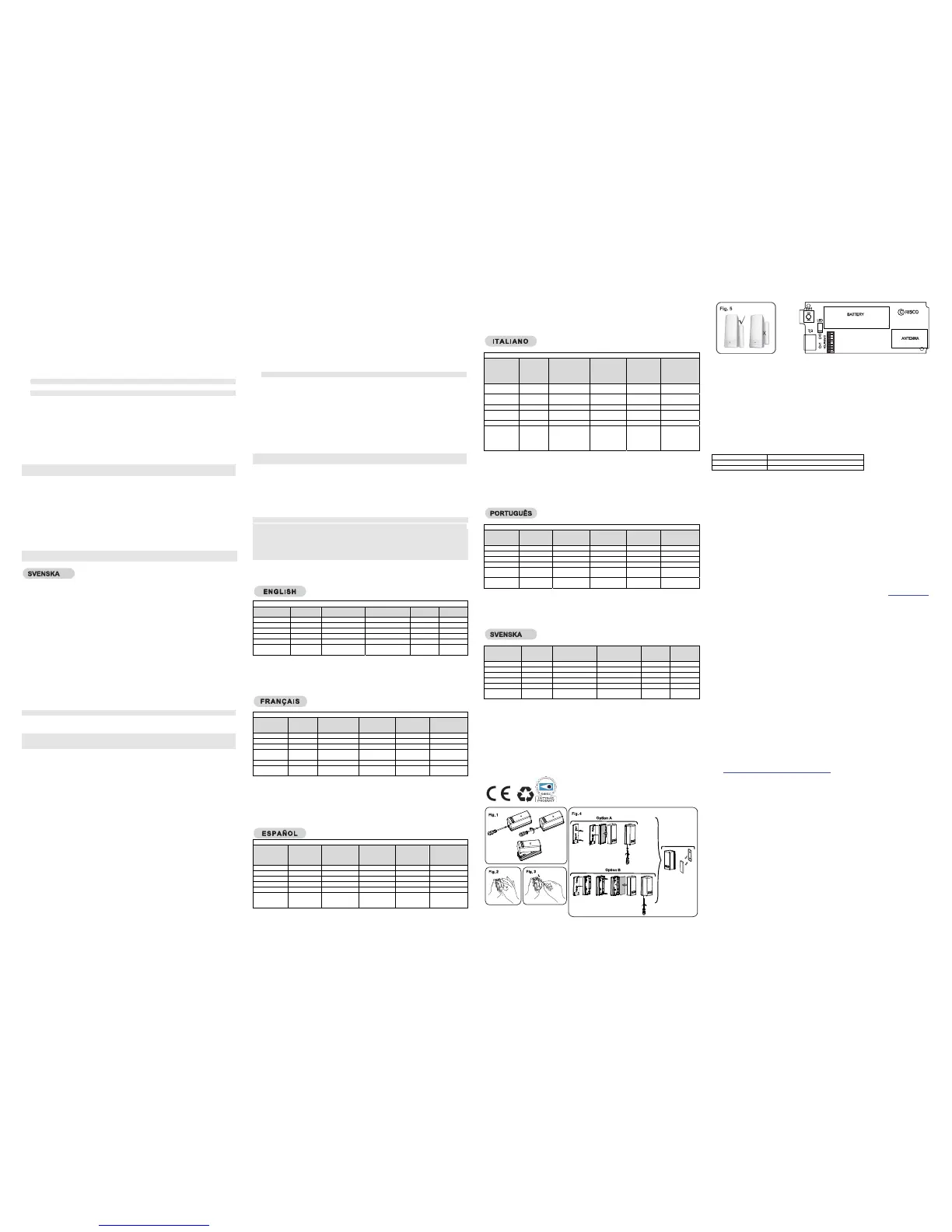
Nota: a marca na caixa plástica do imã deve ser colocada em frente à marca na caixa do
transmissor (Fig. 5).
1. ALLMÄNT
Detta är en övervakad sändare med universal ingång för externa sensorer. Den fungerar till trådlösa
system från Risco Group och drivs av ett standard 3-volts lithium batteri.
EGENSKAPER:
Räckvidd upp till 300m i fri luft
RF hög/låg effekt
Använder en 16 miljoner slumpvisa koder för inlärning
Mikroprocessorbaserad
Förlängd batteritid
Helt övervakad
Batterisparfunktion
Ställbar responstid:
Snabb för vibrationsdetektorer etc.
Normal – för magnetkontakter etc.
Valbar universalingång- NC eller NO
Sabotageskydd för bortbrytning och öppning
Försedd med sensorskydd för att förhindra falsklarm på grund av insekter
Lins med pigment för skydd mot vitt ljus, för att förhindra falsklarm
2. ARBETSLÄGEN
NORMALT ARBETSLÄGE: Sändaren skickar ett larm när den aktiveras (magnetdelen förs bort från
sändaren eller kontakten öppnas) och en återställning när status på magnet eller ingång återgår till
normalläge. Med batterisparfunktion aktiverad kan endast 1 larm sändas per 2.5 minuts period.
Not: Extra sändningar av larm och återställning kan genereras genom att öppna/stänga extern kontakt
INLÄRNING: Ett inlärningsmeddelande genereras genom att hålla ner båda sabotagekontakterna
(mot vägg och i kapsling) i minst 3 sekunder. Not: Vid sändning av övervakningsmeddelande skickar
sändaren med status på batteri, magnet och ingång.
Not: Utför alltid ett räckviddstest innan slutlig montering för att verifiera signalstyrka.
Not: At installation or replacement, perform a Communication Check with the receiver to verify
proper operation.
3. LYSDIOD INDIKERING
Vid varje aktivering tänds lysdioden en kort stund. Vid lågt batteri blinkar indikeringen vid varje
aktivering.
4. INSTALLATION
Steg1: Att tänka på
Välj en monteringsplats som på bästa sätt täcker det område som ska skyddas (se
täckningsområden ovan).
Tänk då också på följande:
Montera inte detektorn så den utsätts för direkt solljus eller i närheten av värmekällor eller
större metallföremål.
Detektorns avkänningszoner bör avslutas i vägg eller golv och inte ligga mot fönsterrutor
eller gardiner.
Välj monteringshöjd beroende på önskat täckningsområde.
Steg 2: Registrera detektorn i systemet
Detektorn iWave måste identifiera sig för systemets mottagare. Detta kan göras genom att enhetens
11-siffriga serienummer skrivs in eller
genom att läsa in enheten via radio. För att skriva in detektorns serienummer, var vänlig se
instruktioner i Agility Installationsmanual.
INSTÄLLNING AV DIP-SWITCHAR
T72M Sändaren har 8 dip-switchar:
1. Används för att fördubbla antalet radiosändningar vid aktivering (för att unvika interferens eller
öka chansen att radiosändningen når fram under dåliga förhållanden).
ON: Fördubbling av radiosändningen.
OFF*: Normal sändning.
2. Används för att koppla ur sabotage mot vägg
ON: Sabotagekontakt urkopplad (intern är inkopplad)
OFF*: Sabotage mot vägg inkopplad (intern och mot vägg inkopplade)
3. Övervakningssignal
ON: Var 65:e minut
OFF*: Var 15:e minut
4. Magnetkontakt in/urkopplad
ON: Urkopplad
OFF*: Inkopplad
5. Balansering av universalingången
ON: Normalt sluten (NC)
OFF*: Normalt öppen
6. Responstid för universalingången
ON: Normal-500 ms (för magnetkontakter etc.)
OFF*: Snabb-10ms (för rullport och vibrationsdetektor t.ex.)
7. Batterisparfunktion
ON: Sändaren går ner i viloläge i 2.5 minut efter sändning av öppning eller stängning
OFF*: Ingen batterisparfunktion, sändaren är alltid aktiv.
Not: Följande gäller oavsett inställning ovan:
1. Urkoppling av slinga till universalingång genererar larm efter 500ms
2. Öppning och stängning av magnetkontakt genererar extra sändning av larm och återställning.
8. Används för att justera sändarens RF-uteffekt.
ON: Låg sändningsstyrka (när sändaren är nära mottagare).
Hög sändningsstyrka.
*= Fabriksinställning
5 ÖPPNA SÄNDAREN (Fig. 1)
6. INLÄRNING AV SÄNDAREN TILL MOTTAGARE
a. Ställ mottagaren i Inlärningsläge
b. Sätt i batteriet (Figur 2.) Aktivera en radiosändning genom att hålla ner båda
sabotagekontakterna i minst 3 sekunder. Verifiera att mottagaren bekräftat inlärningen.
c. Avsluta inlärningsläget
Not: Upprepa proceduren med inlärning genom att hålla ner sabotagekontakterna längre och
eventuellt närmare mottagaren.
7. VAL AV MONTERINGSPLATS
a. Placera sändaren optimalt för radiokommunikation och nära eventuell trådbunden kontakt.
Placera sändaren så högt som möjligt.
b. Montera sändaren temporärt med dubbelsidig tejp.
c. Skapa en sändning genom att aktivera magnetkontakten eller den trådbundna ingången. Om
sändningen inte når fram kan sändaren behöva omplaceras.
8. SLUTLIG MONTERING
Dela på enheten (Fig. 3) och montera alla delar (Fig. 4). Koppla in eventuell trådbunden slinga.
Not: Observera märkningen i plasten som indikerar hur delarna ska vara positionerade (Fig. 5).
Notes.
1. ON: Innebär 2.5 minuter batterispar, OFF är sändaren alltid aktiv
2. Välj SNABB om kontakt för rulljalusi eller vibration är inkopplad (DIP 6).
3. Återställning skickas endast om magnet är stängd och extern ingång är stängd. Annars
kvarstår enheten i larm (öppet läge).
4. Återställning skickas endast om magnet är stängd och extern ingång är öppen. Annars
kvarstår enheten i larm (öppet läge).
När batteriet bytts ut och sabotagekontakten sluts ställer sig detektorn automatiskt i gångtestläge
under 20 minuter.
VARNING: Risk för hög värme och explosion om fel batterityp används. Slutkörda batterier ska
deponeras på rätt sätt.
FOR QUICK INSTALLATION: DIPSWITCH SETTING PER APPLICATION
APPLICATION
ITEM
MAGNET
ONLY
MAGNET+N.C.
INPUT (T.B.)
MAGNET+N.O.
INPUT (T.B)
N.C. INPUT
(T.B)
N.O. INPUT
(T.B)
DIPSWITCH 7 (1) HOLD ON HOLD ON HOLD ON HOLD ON HOLD ON
DIPSWITCH 6 (2) ON: SLOW ON: SLOW ON: SLOW ON: SLOW ON: SLOW
DIPSWITCH 5 OFF: N.O. ON: N.C. OFF: N.O. ON: N.O. OFF: N.O.
DIPSWITCH 4 OFF OFF OFF ON ON
TB FREE T.B. USED T.B. USED T.B. USED T.B. USED
LOGIC (MAGNET
& T.B)
MAGNET
ONLY
AND (3) AND (4) T.B. ONLY T.B. ONLY
1. HOLDON means 2.5 minutes dead time, in HOLDOFF there is no dead time.
2. In case of using fast respond shock sensor, choose FAST (Dipswitch 6).
3. Only if the magnet is closed and the external input (T.B) is closed, the unit will send restore.
Otherwise the unit is in open (alarm) state.
4. Only if the magnet is closed and the external input (T.B) is open, the unit will send restore.
Otherwise the unit is in open (alarm) state.
POUR UNE INSTALLATION RAPIDE: JUMPER INSTALLATION POUR CHAQUE APPLICATION
APPLICATION
IMANT
SEULEMENT
AIMANT +N.C.
INFORMATION
(T.B.)
AIMANT +N.O.
INFORMATION
(T.B.)
N.C.
INFORMATION
(T.B)
NO.
INFORMATION
(T.B)
DIPSWITCH 7 (1) IN (HOLD-ON) IN (HOLD-ON) IN (HOLD-ON) IN (HOLD-ON) IN (HOLD-ON)
DIPSWITCH 6 (2) LENTEMENT LENTEMENT LENTEMENT LENTEMENT LENTEMENT
DIPSWITCH 5 NO. N.C. N.C. NO. NO.
DIPSWITCH 4 OUVERT-
EXTERIEUR
OUVERT-
EXTERIEUR
OUVERT-
EXTERIEUR
FERME-
INTERIEUR
FERME-
INTERIEUR
TB LI BRE MEN T UT ILI SAT ION T. B. UTILISATION T.B. UTILISATION T.B. UTILISATION T.B.
LOGIC
(EMANT & T.B)
AIMANT
SEULEMENT
ET (3) ET (4) T.B.
SEULEMENT
T.B. SEULEMENT
1. «Maintenu» (= HOLD ON) signifie 2min.30 de temps mort, par opposition à HOLD OFF où il n'y a
pas de temps mort.
2. Si vous utilisez un détecteur de chocs à réaction rapide, sélectionnez l'option «rapide» (FAST)
(Dipswitch 6).
3. Ce n'est que si l'aimant est fermé et que l'entrée externe (T.B) est fermée que l'appareil enverra un
message de remise en service. Sinon, il reste en position (d'alarme).
4. Ce n'est que si l'aimant est fermé et que l'entrée externe (T.B) est ouverte que l'appareil enverra un
message de remise en service. Sinon, il reste en position (d'alarme).
PARA UNA INSTALACION RAPIDA: CONFIG. MICROINTERRUPTORES EN FUNCIÓN DE LA APLICACIÓN
APLICACIÓN
SÓLO
CONTACTO
MAGNÉTICO
CONTACTO
MAGNÉTICO +
ENTRADA N.C.
(T.B)
CONTACTO
MAGNÉTICO +
ENTRADA N.A.
(T.B)
ENTRADA N.C.
(T.B)
NO.
INFORMATION
(T.B)
DIP 7 (1) ON (REPOSO) ON (REPOSO) ON (REPOSO) ON (REPOSO) ON (REPOSO)
DIP 6 (2) ON (LENTO) ON (LENTO) ON (LENTO) ON (LENTO) ON (LENTO)
DIP 5 OFF(N.A.) OFF(N.C.) OFF(N.A.) ON (N.C.) OFF (N.A.)
DIP 4 OFF OFF OFF ON ON
T.B. LIBRE T.B UTILIZADA T.B UTILIZADA T.B UTILIZADA T.B UTILIZADA
LÓGICA
(MAGNÉTICO Y
T.B)
SÓLO
MAGNÉTICO
AND (Y) (3) AND (Y) (4) SÓLO T.B SÓLO T.B
1. REPOSO significa 2,5 minutos de tiempo muerto entre ransmisiones de alarma para ahorrar
batería. En la posición OFF no hay tiempos muertos.
2. En caso de utilizar detectores inerciales de respuesta rápida, poner el DIP 6 en posición OFF (RAPIDO).
3. La unidad mandará restauración sólo si el magnético (T.B) está cerrada. De lo contrario la unidad
está abierta (Alarma).
4. La unidad mandará la señal de restauración sólo si el magnético está cerrado y la entrada externa
(T.B) está abierta. De lo contrario la unidad está abierta (Alarma).
INSTALLAZIONE RAPID
: CONFIG. MICROINTERRUTTORI IN FUNZIONE DELL’APPLICAZIONE
Z/
ITEM
SOLO
CONTATTO
MAGNETICO
INTERNO
CONTATTO
MAGNETICO INT. +
INGRESSO
ESTERNO N.C. (T.B)
CONTATTO
MAGNETICO INT.
+ INGRESSO
ESTERNO N.O.
(T.B)
INGRESSO
ESTERNO N.C.
(T.B)
INGRESSO
ESTERNO N.O.
(T.B)
Microinterruttore 7
(NOTA 1)
ON (BLOCCO
2,5 MIN)
ON (BLOCCO 2,5
MIN)
ON (BLOCCO 2,5
MIN)
ON (BLOCCO
2,5 MIN)
ON (BLOCCO 2,5
MIN)
Microinterruttore 6
(NOTA 2)
ON (RISP.
LENTA)
ON (RISP. LENTA) ON (RISP.
LENTA)
ON (RISP.
LENTA)
ON (RISP. LENTA)
Microinterruttore 5 OFF (N.O.) ON (N.C.) OFF (N.O.) ON (N.C.) OFF (N.O.)
Microinterruttore 4 OFF
(APERTO)
OFF (APERTO) OFF (APERTO) ON (CHIUSO) ON (CHIUSO)
TB LIBERO T.B USATO T.B USATO T.B USATO T.B USATO
LOGICA
CONTATTO
INTERNO &
INGRESSO
ESTERNO T.B
SOLO
CONTATTO
MAGNETICO
INTERNO
LOGICA AND
(NOTA 3)
LOGICA AND
(NOTA 4)
SOLO
INGRESSO
ESTERNO T.B
SOLO INGRESSO
ESTERNO T.B
1. La funzione BLOCCO 2,5 m. abilita un tempo di blocco trasmissioni di 2.5 minuti dopo una
segnalazione (e relativo ripristino), con il relativo microinterruttore in OFF, il blocco trasmissioni non
è attivo per cui il trasmettitore trasmette sempre ogni variazione di stato.
2. Per usare una risposta veloce del circuito per i rivelatori inerziali, selezionare RISPOSTA VELOCE
posizionando il microinterruttore 6 in OFF.
3. Solo se il contatto magnetico interno è chiuso e l’ingresso esterno (T.B) è chiuso l’unità trasmette il
segnale di ripristino. In caso contrario l’unità è in stato “aperto” (allarme).
4. Solo se il contatto magnetico interno è chiuso e l’ingresso esterno (T.B) è aperto l’unità trasmette
ilsegnale di ripristino. In caso contrario l’unità è in stato “aperto” (allarme).
PARA UMA RÁPIDA INSTALAÇÃO:
JUSTE DOS JUMPERS POR APLIC
ENTRADA
N.C.
(Term Entrada)
IM
ENTRADA
N.O.
(Term Entrada)
ENTRADA N.C.
(Term Entrada)
ENTRADA N.O.
(Term Entrada)
DIPSWITCH 7 (1) IN (HOLD-ON) IN (HOLD-ON) IN (HOLD-ON) IN (HOLD-ON) IN (HOLD-ON)
DIPSWITCH 6 (2) Ret. (LENTO) Ret. (LENTO) Ret. (LENTO) Ret. (LENTO) Ret. (LENTO)
DIPSWITCH 5 Ret. (NO.) Coloc (N.C.) Ret. (NO.) Coloc (N.C.) Ret. (NO.)
DIPSWITCH 4 Ret. (ABERTO) Ret. (ABERTO) Ret. (ABERTO) IN (FECHADO) IN (FECHADO)
(Term Entrada) LIVRE T Entrada USADO T Entrada USADO T Entrada
USADO
T Entr. USADO
LOGICA
(IMÃ e Terminal)
SOMENTE IMÃ (Lógica E)
(NOTA 3)
Y
(NOTA 4)
SOMENTE
(Term Entrada)
SOMENTE
(Term Entrada)
1.HOLD ON significa 2.5 minutos de intervalo, em HOLD OFF não há intervalo.
2. En caso de usar reação rápida para sensores de vibração ajuste Para FAST (Dipswitch 6).
3. Apenas se o detector estiver restaurado, e as entradas externas estiverem a unidade en viará um
sinal de restauração.
4. Penas se o detector estiver restaurado, e as entradas externas estiverem abertas a unidade
enviará um sinal de restauração. Se não, a unidade estará aberta (em alarme).
TYP/
SWITCH
ENDAST
MAGNET
MAGNET+N.C.
INGÅNG (TB)
MAGNET+N.O.
INGÅNG (T.B)
N.C.
INGÅNG
(T.B)
N.O.
INGÅNG
(T.B)
DIPSWITCH 7 (1) OFF OFF OFF OFF OFF
DIPSWITCH 6 (2) ON: Normal ON: Normal ON: Normal ON: Normal ON: Normal
DIPSWITCH 5 OFF: N.O. ON: N.C. OFF: N.O. ON: N.C. OFF: N.O.
DIPSWITCH 4 OFF OFF OFF ON ON
INGÅNG Ingen funktion Används Används Används Används
LOGIK (MAGNET
& INGÅNG)
Endast
magnet
OCH(3) OCH(4) Endast
ingång
Endast
ingång
1. ON: Innebär 2.5 minuter batterispar, OFF är sändaren alltid aktiv.
2. Välj SNABB om kontakt för rulljalusi eller vibration är inkopplad (DIP 6).
3. Återställning skickas endast om magnet är stängd och extern ingång är stängd. Annars kvarstår
enheten i larm (öppet läge).
4. Återställning skickas endast om magnet är stängd och extern ingång är öppen. Annars kvarstår
enheten i larm (öppet läge).
NOTE: This product should be tested at least once a week
RED Compliance Statement:
Hereby, RISCO Group declares that this product is in compliance with the essential requirements
and other relevant provisions of Directive 2014/53/EU. For the CE Declaration of Conformity please
refer to our website: www.riscogroup.com
EN 50131-2-6,EN50131-5-3, Grade 2 Environmental class II (Modell: RWT72M) EN 50131-
1,EN50131-5-3, Grade 2 Environmental class II (Modell: WL T72C), SSF 1014 v4, & Larmklass R
SPECIFICATIONS
ELECTRICAL
Batter
pe: CR123 3V Lithium Batter
Current Consumption: 30μA standb
; 13mA transmission
Frequenc
: 868.65 MHz / 433.92 MHz
Dead Time
: 2.5 minutes
Supervision Transmission: Ever
15/65 minutes
Modulation T
e Threshold: 2.5V
PHYSICAL
Size: 81 x 35 x 32 mm
temperature: -10°C to 55°C
e temperature: -20°C to 60°C
Specifications are subject to change without prior notice. Should any questions arise please contact
your supplier.
MODELS AVAILABLE
Model Description
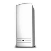
WL 72C WL Universal Transmitte
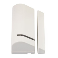
RWT72M WL Door/Window Contac
Standard Limited Product Warranty (“Limited Warranty”)
RISCO Ltd. (“RISCO") guarantee RISCO’s hardware products (“Products”) to be free from defects in
materials and workmanship when used and stored under normal conditions and in accordance with the
instructions for use supplied by RISCO, for a period of (i) 24 months from the date of delivery of the Product (
the “Warranty Period”). This Limited Warranty covers the Product only within the country where the Product
was originally purchased and only covers Products purchased as new.
Contact with customers only. This Limited Warranty is solely for the benefit of customers who purchased
the Products directly from RISCO or from an authorized distributor of RISCO. RISCO does not warrant the
Product to consumers and nothing in this Warranty obligates RISCO to accept Product returns directly from
end users who purchased the Products for their own use from RISCO’s customer or from any installer of
RISCO, or otherwise provide warranty or other services to any such end user directly. RISCO’s authorized
distributor or installer shall handle all interactions with its end users in connection with this Limited Warranty.
RISCO’s authorized distributor or installer shall make no warranties, representations, guarantees or
statements to its end users or other third parties that suggest that RISCO has any warranty or service
obligation to, or any contractual privy with, any recipient of a Product.
Remedies. In the event that a material defect in a Product is discovered and reported to RISCO during the
Warranty Period, RISCO shall accept return of the defective Product in accordance with the below RMA
procedure and, at its option, either (i) repair or have repaired the defective Product, or (ii) provide a
replacement product to the customer.
Return Material Authorization. In the event that you need to return your Product for repair or replacement,
RISCO will provide you with a Return Merchandise Authorization Number (RMA#) as well as return
instructions. Do not return your Product without prior approval from RISCO. Any Product returned without a
valid, unique RMA# will be refused and returned to the sender at the sender’s expense. The returned Product
must be accompanied with a detailed description of the defect discovered (“Defect Description”) and must
otherwise follow RISCO’s then-current RMA procedure published in RISCO’s website at www.riscogroup.com
in connection with any such return. If RISCO determines in its reasonable discretion that any Product
returned by customer conforms to the applicable warranty (“Non-Defective Product”), RISCO will notify the
customer of such determination and will return the applicable Product to customer at customer’s expense. In
addition, RISCO may propose and assess customer a charge for testing and examination of Non-Defective
Product.
Entire Liability. The repair or replacement of Products in accordance with this Limited Warranty shall be
RISCO’s entire liability and customer’s sole and exclusive remedy in case a material defect in a Product is
discovered and reported as required herein. RISCO’s obligation and this Limited Warranty are contingent
upon the full payment by customer for such Product and upon a proven weekly testing and examination of the
Product functionality.
Limitations. This Limited Warranty is the only warranty made by RISCO with respect to the Products. The
warranty is not transferable to any third party. To the maximum extent permitted by applicable law, this
Limited Warranty shall not apply and will be void if: (i) the conditions set forth above are not met (including,
but not limited to, full payment by customer for the Product and a proven weekly testing and examination of
the Product functionality); (ii) if the Products or any part or component thereof: (a) have been subjected to
improper operation or installation; (b) have been subject to neglect, abuse, willful damage, abnormal working
conditions, failure to follow RISCO’s instructions (whether oral or in writing); (c) have been misused, altered,
modified or repaired without RISCO’s written approval or combined with, or installed on products, or
equipment of the customer or of any third party; (d) have been damaged by any factor beyond RISCO’s
reasonable control such as, but not limited to, power failure, electric power surges, or unsuitable third party
components and the interaction of software therewith or (e) any failure or delay in the performance of the
Product attributable to any means of communication provided by any third party service provider, including,
but not limited to, GSM interruptions, lack of or internet outage and/or telephony failure. BATTERIES ARE
EXPLICITLY EXCLUDED FROM THE WARRANTY AND RISCO SHALL NOT BE HELD RESPONSIBLE OR
LIABLE IN RELATION THERETO, AND THE ONLY WARRANTY APPLICABLE THERETO, IF ANY, IS THE
BATTERY MANUFACTURER'S WARRANTY. RISCO does not install or integrate the Product in the end
user’s security system and is therefore not responsible for and cannot guarantee the performance of the end
user’s security system which uses the Product or which the Product is a component of.
This Limited Warranty applies only to Products manufactured by or for RISCO. Further, this Limited Warranty
does not apply to any software (including operating system) added to or provided with the Products or any
third-party software, even if packaged or sold with the RISCO Product. Manufacturers, suppliers, or third
parties other than RISCO may provide their own warranties, but RISCO, to the extent permitted by law and
except as otherwise specifically set forth herein, provides its Products “AS IS”. Software and applications
distributed or made available by RISCO in conjunction with the Product (with or without the RISCO brand),
including, but not limited to system software, as well as P2P services or any other service made available by
RISCO in relation to the Product, are not covered under this Limited Warranty. Refer to the Terms of Service
at: https://riscocloud.com/ELAS/WebUI/UserLogin/License for details of your rights and obligations with
respect to the use of such applications, software or any service. RISCO does not represent that the Product
may not be compromised or circumvented; that the Product will prevent any personal injury or property loss
by burglary, robbery, fire or otherwise, or that the Product will in all cases provide adequate warning or
protection. A properly installed and maintained alarm may only reduce the risk of a burglary, robbery or fire
without warning, but it is not insurance or a guarantee that such will not occur or will not cause or lead to
personal injury or property loss. CONSEQUENTLY, RISCO SHALL HAVE NO LIABILITY FOR ANY
PERSONAL INJURY, PROPERTY DAMAGE OR OTHER LOSS BASED ON ANY CLAIM AT ALL
INCLUDING A CLAIM THAT THE PRODUCT FAILED TO GIVE WARNING.
EXCEPT FOR THE WARRANTIES SET FORTH HEREIN, RISCO AND ITS LICENSORS HEREBY
DISCLAIM ALL EXPRESS, IMPLIED OR STATUTORY, REPRESENTATIONS, WARRANTIES,
GUARANTEES, AND CONDITIONS WITH REGARD TO THE PRODUCTS, INCLUDING BUT NOT LIMITED
TO ANY REPRESENTATIONS, WARRANTIES, GUARANTEES, AND CONDITIONS OF
MERCHANTABILITY, FITNESS FOR A PARTICULAR PURPOSE, TITLE AND WARRANTIES AGAINST
HIDDEN OR LATENT DEFECTS, TO THE EXTENT PERMITTED BY LAW. WITHOUT LIMITING THE
GENERALITY OF THE FOREGOING, RISCO AND ITS LICENSORS DO NOT REPRESENT OR WARRANT
THAT: (I) THE OPERATION OR USE OF THE PRODUCT WILL BE TIMELY, SECURE, UNINTERRUPTED
OR ERROR-FREE; (ii) THAT ANY FILES, CONTENT OR INFORMATION OF ANY KIND THAT MAY BE
ACCESSED THROUGH THE PRODUCT SHALL REMAIN SECURED OR NON DAMAGED. CUSTOMER
ACKNOWLEDGES THAT NEITHER RISCO NOR ITS LICENSORS CONTROL THE TRANSFER OF DATA
OVER COMMUNICATIONS FACILITIES, INCLUDING THE INTERNET, GSM OR OTHER MEANS OF
COMMUNICATIONS AND THAT RISCO’S PRODUCTS, MAY BE SUBJECT TO LIMITATIONS, DELAYS,
AND OTHER PROBLEMS INHERENT IN THE USE OF SUCH MEANS OF COMMUNICATIONS. RISCO IS
NOT RESPONSIBLE FOR ANY DELAYS, DELIVERY FAILURES, OR OTHER DAMAGE RESULTING
FROM SUCH PROBLEMS. RISCO WARRANTS THAT ITS PRODUCTS DO NOT, TO THE BEST OF ITS
KNOWLEDGE, INFRINGE UPON ANY PATENT, COPYRIGHT, TRADEMARK, TRADE SECRET OR
OTHER INTELLECTUAL PROPERTY RIGHT IN ANY EVENT RISCO SHALL NOT BE LIABLE FOR ANY
AMOUNTS REPRESENTING LOST REVENUES OR PROFITS, PUNITIVE DAMAGES, OR FOR ANY
OTHER INDIRECT, SPECIAL, INCIDENTAL, OR CONSEQUENTIAL DAMAGES, EVEN IF THEY WERE
FORESEEABLE OR RISCO HAS BEEN INFORMED OF THEIR POTENTIAL.
WARNING: This product should be tested at least once a week.
CAUTION: Risk of explosion if battery is replaced by an incorrect type. Dispose of used batteries according
to local regulations.
© RISCO Group 02/17 5IN2515 B
C
ON
3
1
2
4
5678
+
-
1
2
 Loading...