Abb./Fig./Fig. 1: Beigelegtes Zubehör / Accessories provided / Accessoires
joints
Abb./Fig./Fig. 2: Montage und Elektroanschluss / Mounting and electrical
connection / Montage et raccordement électrique
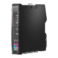
Abb./Fig./Fig. 3: Bedienfeld, Stecker und Anschlüsse / Operator panel, plugs
and connectors / Panneau de commande, fiches et raccorde-
ments
2a
2b
2c
0.2…2.5 mm²
(24…13 AWG)
2
1
1
2
7 mm
CAN 1
CAN 2
1
2
3
4
6
5
7
8
9101112
16 15 14 13
DE
Installationsanleitung und Kurz-Bedienungsanleitung
IoT Interface (SK 3124.300)
1 Hinweise zur Dokumentation
Diese Installations- und Kurz-Bedienungsanleitung richtet sich an versiertes Fach-
personal und enthält nur die wichtigsten Informationen zur Montage, Installation und
Funktion des IoT Interface.
1.1 Mitgeltende Unterlagen
Montage-, Installations- und Bedienungsanleitung IoT Interface.
Sie ist unter www.rittal.de verfügbar und enthält die vollständigen anwendungsrele-
vanten Informationen und technischen Daten zum IoT Interface in Hinblick auf:
– Details zum elektrischen Anschluss
– Funktionen und Services
– Konfigurationsmöglichkeiten
– Detaillierte Bedienungsanweisungen
– Fehlerbehebung
2 Sicherheitshinweise
– Montage und Installation des Geräts dürfen nur durch versiertes Fachpersonal er-
folgen.
– Ein Netzspannungsanschluss bzw. eine Netzspannungsverkabelung darf nur
durch eine versierte Elektrofachkraft erfolgen.
– Das Gehäuse des IoT Interface darf nicht geöffnet werden.
– Das IoT Interface darf nicht in Kontakt mit Wasser, aggressiven oder entzündba-
ren Gasen und Dämpfen kommen.
– Das IoT Interface darf nur innerhalb der spezifizierten Umgebungsbedingungen
betrieben werden (vgl. Abschnitt 3.4).
– Das IoT Interface ist nur für den Gebrauch in Innenräumen bestimmt.
3 Produktbeschreibung
3.1 Funktionsbeschreibung
Das IoT Interface dient zur Vernetzung und Administration von Rittal Komponenten,
wie z. B. Blue e+ Kühlgeräten, Blue e+ Chillern, Smart Monitoring System u. ä., mit
kundeneigenen Monitoring- und/oder Energiemanagement-Systemen. Die erzeug-
ten Datenmengen können zur weitergehenden Datensammlung und -verarbeitung
verwendet werden. Dies ermöglicht eine langfristige Aufzeichnung und Auswertung
von Gerätedaten, Zuständen und Systemmeldungen.
3.2 Bestimmungsgemäße Verwendung
Das IoT Interface dient ausschließlich zur Vernetzung von Rittal Komponenten im In-
dustriebereich. Eine andere Verwendung ist nicht bestimmungsgemäß.
3.3 Lieferumfang
– IoT Interface
– Beigelegtes Zubehör (Abb. 1)
– Installations- und Kurz-Bedienungsanleitung
3.4 Betriebsbedingungen
Das IoT Interface darf nur unter folgenden Betriebsbedingungen betrieben werden:
4Montage
4.1 Montageanweisung
Die Montage des IoT Interface erfolgt entweder auf einer Hutschiene gemäß Abb. 2a
oder direkt an einem Blue e+ Kühlgerät gemäß Abb. 2b.
5 Installation und Bedienung
5.1 Bedien- und Anzeigeelemente
Die Bedien- und Anzeigeelemente sind in Abb. 3 dargestellt.
Legende zu Abb. 3
1 LEDs Netzwerk-Verkehr
2 LEDs CAN-Bus-Anschluss 1
3 LEDs CAN-Bus-Anschluss 2
4 LED Datenübertragung Klimageräte (links)/Multi-LED zur Statusanzeige
(rechts)
5 Versteckte Reset-Taste
6 Taster zur Quittierung von Alarmen bzw. Meldungen
7SD-Card-Einschub
8 Micro-USB-Anschluss zur Konfiguration
9USB-Host-Anschluss
10 Anschluss externer Temperaturfühler
11 Ethernet-Schnittstelle RJ 45
12 Spannungsversorgung 24 V (Direktanschluss)
13 Anschluss Rittal Klimagerät 2 (z. B. Schaltschrank-Kühlgerät Blue e+)
14 Anschluss Rittal Klimagerät 1 (z. B. Schaltschrank-Kühlgerät Blue e+)
15 CAN-Bus-Anschluss 2 (Daisy Chain) für CMC III Sensoren oder Smart Mo-
nitoring System
16 CAN-Bus-Anschluss 1 (Daisy Chain) für CMC III Sensoren oder Smart Mo-
nitoring System
Temperatur-Einsatzbereich +0°C…+70°C
Feuchtigkeits-Einsatzbereich 10 %…90 % relative Feuchte, nicht kon-
densierend
Schutzart IP 20 nach IEC 60 529
EN Installation Guide and Short User's Guide
IoT interface (SK 3124.300)
1 Notes on documentation
This installation and short user's guide is intended for experienced trained special-
ists and contains only the most important information concerning the assembly, in-
stallation and function of the IoT interface.
1.1 Associated documents
Assembly, installation and user's guide IoT interface.
It is available at www.rittal.com and contains the complete application-relevant in-
formation and technical data for the IoT interface with regard to:
– Details concerning the electrical connection
–Functions and services
– Configuration possibilities
– Detailed operating instructions
– Troubleshooting
2 Safety instructions
– Assembly and installation of the device may only be performed by experienced
trained specialists.
– A mains power connection or wiring to the mains power may only be performed
by an experienced electrician.
– The IoT interface housing must not be opened.
– The IoT interface may not come in contact with water, aggressive or inflammable
gases and vapours.
– The IoT interface may only be operated within the specified environmental condi-
tions (see section3.4).
– The IoT interface is restricted to indoor use only.
3 Product description
3.1 Functional description
The IoT interface facilitates the interconnection and administration of Rittal compo-
nents (such as Blue e+ cooling units, Blue e+ chillers, Smart Monitoring System)
with in-house customer monitoring systems and/or energy management systems.
The generated data sets can be used for further data collection and processing. This
permits a long-term recording and evaluation of device data, statuses and system
messages.
3.2 Proper use
The IoT interface is used exclusively for interconnecting Rittal components in the in-
dustrial area. Any other use is not permitted.
3.3 Scope of delivery
–IoT interface
– Accessories provided (fig. 1)
– Installation and Short User's Guide
3.4 Operating conditions
The IoT interface may only be operated under the following operating conditions:
4Assembly
4.1 Assembly instructions
The IoT interface is mounted either on a top hat rail as shown in fig. 2a or directly on
a Blue e+ cooling unit as shown in fig. 2b.
5 Installation and operation
5.1 Operating and display elements
The operating and display elements are shown in fig. 3.
Key for fig. 3
1 Network traffic LEDs
2 CAN bus connection 1 LEDs
3 CAN bus connection 2 LEDs
4 LED data transmission climate control units (left) / multi-LED for status dis-
play (right)
5 Hidden reset key
6 Push-button for acknowledging alarms and messages
7SD card slot
8 Micro-USB connection for configuring
9 USB-host connection
10 Connection of an external temperature sensor
11 Ethernet interface, RJ 45
12 24 V power supply (direct connection)
13 Rittal cooling unit 2 connection (e.g. Blue e+ enclosure cooling unit)
14 Rittal cooling unit 1 connection (e.g. Blue e+ enclosure cooling unit)
15 CAN bus connection 2 (daisy-chain) for CMC III sensors or Smart Monitoring
System
16 CAN bus connection 1 (daisy-chain) for CMC III sensors or Smart Monitoring
System
Temperature operational range +0°C…+70°C
Humidity operational range 10%…90% relative humidity, non-con-
densing
Protection category IP 20 according to IEC 60 529
FR Notice d'installation et d'utilisation succincte
Interface IoT (SK 3124.300)
1 Remarques relatives à la documentation
Cette notice d'installation et d'utilisation succincte s'adresse à du personnel qualifié
et chevronné et contient uniquement les informations essentielles pour le montage,
l'installation et le fonctionnement de l'interface IoT.
1.1 Autres documents applicables
Notice de montage, d'installation et d'emploi de l'interface IoT.
Elle est disponible sur le site www.rittal.fr et contient les informations complètes re-
latives à la mise en œuvre et aux caractéristiques techniques de l'interface IoT dans
les domaines suivants :
– Détails des raccordements électriques
– Fonctionnement et services
– Possibilités de configuration
– Instructions d'utilisation détaillées
–Dépannage
2 Consignes de sécurité
– Le montage et l'installation de l'appareil doivent être réalisés uniquement par du
personnel qualifié et chevronné.
– Le raccordement au réseau électrique ou le câblage du réseau électrique doit être
réalisé uniquement par un électricien qualifié et chevronné.
– Ne jamais ouvrir le boîtier de l'interface IoT.
– L'interface IoT ne doit pas se trouver en contact d'eau, de gaz et de vapeurs
agressifs ou inflammables.
– L'interface IoT doit être mise en œuvre uniquement dans les conditions ambiantes
spécifiées (voir paragraphe 3.4).
– L'interface IoT est destinée uniquement à une utilisation en intérieur.
3 Description du produit
3.1 Principe de fonctionnement
L'interface IoT sert à la mise en réseau et à la gestion des composants Rittal,
comme p.ex. les climatiseurs Blue e+, les refroidisseurs d'eau Blue e+, le système
de supervision intelligent Smart Monitoring, avec les systèmes de supervision et/ou
de gestion énergétique du client. Les quantités de données générées peuvent en-
suite être utilisées pour l'enregistrement et le traitement des données. Cela permet
un enregistrement et une exploitation à long terme des données des appareillages,
de leur état de fonctionnement et de leurs messages de défaut.
3.2 Utilisation conforme de l'appareil
L'interface IoT sert exclusivement à la mise en réseau des composants Rittal en mi-
lieu industriel. Toute autre utilisation est non conforme.
3.3 Composition de la livraison
–Interface IoT
– Accessoires joints (fig. 1)
– Notice d'installation et d'utilisation succincte
3.4 Conditions de fonctionnement
L'interface IoT doit être mise en œuvre uniquement dans les conditions de fonction-
nement suivantes :
4 Montage
4.1 Instruction de montage
Le montage de l'interface IoT s'effectue soit sur un rail oméga conformément à la
fig. 2a soit directement sur un climatiseur Blue e+ conformément à la fig. 2b.
5 Installation et utilisation
5.1 Organes de commande et de signalisation
Les organes de commande et de signalisation sont présentés sur la fig. 3.
Légende pour la fig. 3
1 Diode pour le trafic réseau
2 Diode pour le raccordement 1 du CAN-Bus
3 Diode pour le raccordement 2 du CAN-Bus
4 Diode pour le transfert des données des climatiseurs (à gauche) / Multi-
diodes pour l'affichage d'état de fonctionnement (à droite)
5 Touche Reset cachée
6 Touche pour l'acquittement des alarmes et des messages
7 Emplacement pour carte SD
8 Raccordement micro-USB pour la configuration
9Port USB Host
10 Raccordement d'une sonde de température externe
11 Interface Ethernet RJ 45
12 Tension d'alimentation 24 V (raccordement direct)
13 Raccordement du climatiseur 2 Rittal (p.ex. climatiseur Blue e+ pour ar-
moire électrique)
14 Raccordement du climatiseur 1 Rittal (p.ex. climatiseur Blue e+ pour ar-
moire électrique)
Plage de température tolérée +0°C…+70°C
Plage d'humidité tolérée 10 %…90 % d'humidité relative, sans
condensation
Indice de protection IP 20 selon la norme CEI 60 529
IoT-A3Quer.fm Seite 1 Donnerstag, 3. Mai 2018 7:03 19