4. Disconnect the positive cable from the battery. Attach the
cable labeled “BATTERY POST” to the positive terminal on the
battery.
Note: If a stop light switch or other accessory must be
energized while towing, make sure to connect the accessory
to the positive side of the battery. DO NOT CONNECT ANY
ACCESSORIES TO THE SOLENOID.
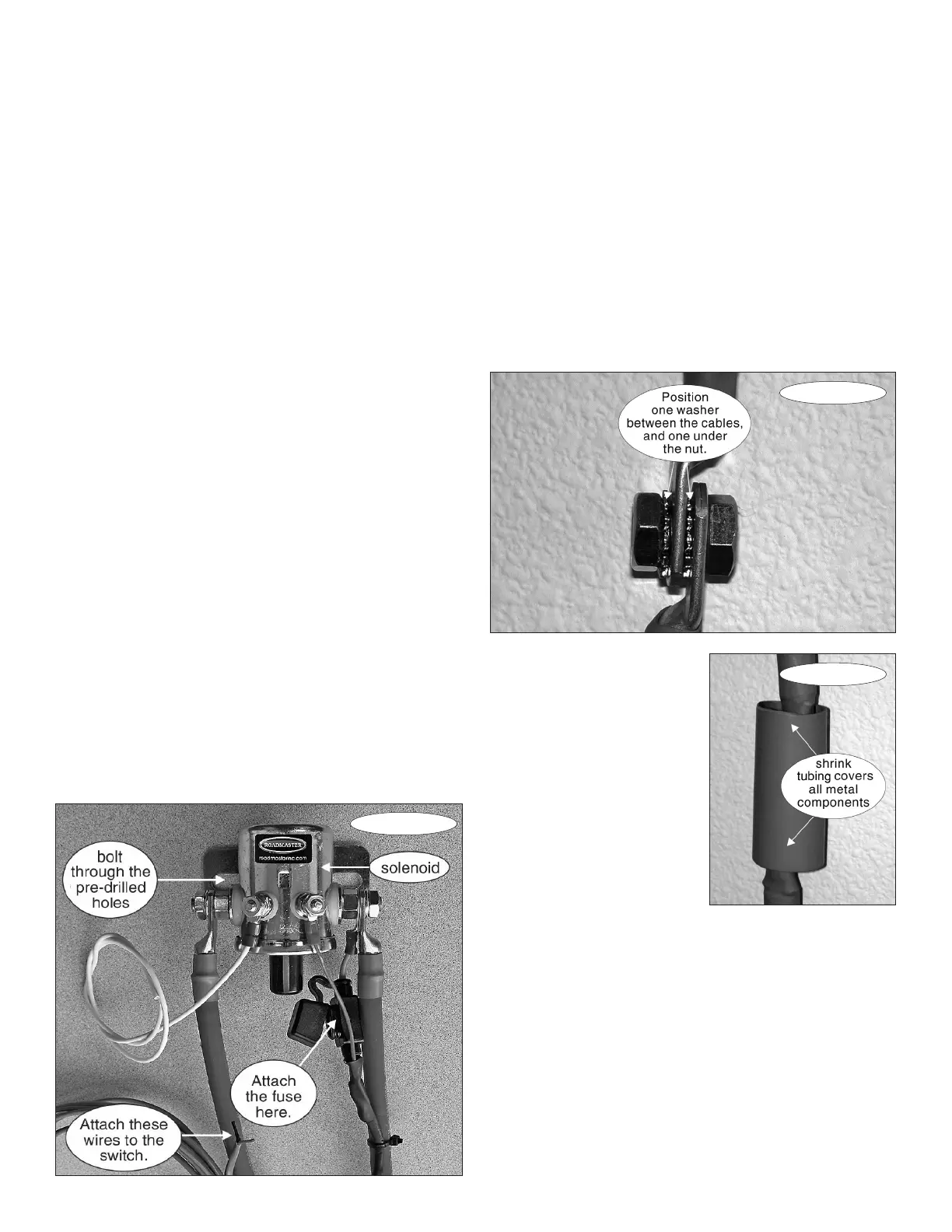
5. Slide the provided section of shrink tubing (Figure 2) over
the cable labeled “POSITIVE CABLE.” Then attach this cable
to the positive cable you just removed from the battery: align the
two ends of the cables so they match. Connect the two cables
together as shown in Figure 2.
Note: It is imperative that the star washers are positioned
as shown.
Note: If the end of the vehicle’s battery cable has a diameter
smaller than 5/16", use a 5/16" drill to enlarge it.
Figure 1
continued from preceding page
Installation
1. Follow the vehicle manufacturer’s instructions to disconnect
the negative battery cable.
2. Choose a mounting location for the solenoid (Figure 1)
inside the engine compartment. This mounting location must
meet the following conditions:
• The mounting point must have a surface of sufficient
strength to hold the solenoid firmly in place.
• There are two cables attached to the solenoid. The end
of the cable labeled “BATTERY POST” must be within reach
of the vehicle’s positive battery post.
• The solenoid will be attached with the two included bolts
and nuts. Make certain that the bolts will not damage any com-
ponents on the other side.
• The solenoid must be grounded by using the provided
white ground wire. Make certain a good ground is available
within two feet of the solenoid.
• The solenoid must be mounted in a location where it is
protected from direct road spray.
• The black tip of the solenoid MUST be pointed downward.
3. Position the solenoid at the mounting location you have
chosen. Drill two ¼" holes for the bolts through the pre-drilled
holes (Figure 1) and attach the solenoid.
Also attach the white ground wire to any good chassis
ground with the included ring terminal and self-tapping screw.
If the cables must be rotated on the solenoid post, then
FOLLOW THESE INSTRUCTIONS CAREFULLY! Put a
wrench on the inside nut and use it to hold the inside nut in
position. Now, loosen the outside nut with a wrench, reposi-
tion the cable and retighten while carefully holding the inside
nut in position. Rotating the inside nut WILL CAUSE NON-
WARRANTY FAILURE of the solenoid.
CAUTION
You WILL destroy the solenoid unless you hold the in-
side nut stationary and ONLY rotate the outside nut. This
damage will not be covered by warranty.
Figure 3
Figure 2
6. Slide the shrink tubing
over the connection as shown
in Figure 3. Be certain no metal
is exposed. Seal the shrink tub-
ing with a heat gun or similar
device.
CAUTION
Make certain that no metal
is exposed on either side of
the shrink tubing. If metal is
exposed, a short circuit may
cause an electrical fire, which
may result in severe damage
to the vehicle.
7. Attach the provided protective loom to both cables.
CAUTION
In order to prevent damage from a short circuit,
cover both cables with the included protective loom. If the
cables are not covered, a short circuit may cause an electri-
cal fire, which may result in severe damage to the vehicle.
Note: Roadmaster recommends using an anti-corrosion
battery terminal spray on all exposed connections.
continued on next page
 Loading...