Do you have a question about the Roadstar CTV-1010XK-XKT and is the answer not in the manual?
Follow safety, servicing, and ESD precautions to prevent damage and protect against potential hazards.
Provides essential precautions for servicing the unit safely and correctly, including handling components and checking insulation.
Details procedures to prevent damage to sensitive electronic components from static electricity.
Details the supported television broadcast systems (e.g., PAL, SECAM).
Lists the channel frequency bands for different broadcast systems.
Specifies the intermediate frequencies used in various broadcast systems.
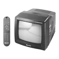
Information about the 10-inch picture tube, including type and deflection angle.
Details the AC and DC power input requirements for the unit.
Specifies the input impedance for the antenna connection.
Indicates the impedance of the unit's speaker.
Details the buttons and indicators located on the front of the television.
Describes connectors and ports on the rear and side of the television, including power and AV inputs.
Covers initial adjustments required after replacing certain components like EEPROM or CRT.
Explains how to enter and navigate the factory service mode for adjustments.
Details the specific parameters and settings available within the service and factory adjustment modes.
Describes the Outcondition Mode used for factory inspection and its functions.
Covers additional adjustments and procedures beyond the factory/service mode.
Provides general guidance and best practices for TV alignment and adjustments.
Explains the automatic degaussing process and when to use an external degaussing coil.
Details how to check and verify the high voltage output and B+ supply levels.
Steps for adjusting the focus control to achieve sharp scanning lines.
Procedure for adjusting the screen voltage for optimal picture brightness and display.
Steps for adjusting color purity and convergence for accurate color reproduction.
Detailed steps for adjusting convergence magnets to align color dots on the screen.
Procedure to optimize picture tube for good black and white levels and brightness.
How to adjust the RF Automatic Gain Control for optimal signal reception.
Steps to adjust picture geometry parameters like height, width, and phase.
Details the features and functionality of the TDA8842 main signal processor IC.
Provides a list of pins and their descriptions for the TDA8842 IC.
Illustrates the internal architecture and signal flow of the TDA884x/5x-N1 series processor.
Details the various functions performed by the TDA884x/5x-N1 series processor, including IF, Audio, Video, RGB, and Sync.
Highlights the key features of the TDA8356 vertical output bridge circuit.
Lists the pins and their respective descriptions for the TDA8356 IC.
Describes the main features of the TDA6107Q triple video output amplifier.
Provides pin configuration and descriptions for the TDA6107Q IC.
Details the features of the L4964 stepdown power switching regulator.
Provides a description of the L4964 power switching regulator's capabilities.
Details the function of each pin for the L4964 power switching regulator.
Illustrates the internal block diagram and functional units of the L4964 power switching regulator.
Highlights the key features of the TDA2007A class AB dual audio power amplifier.
Describes the TDA2007A audio amplifier for stereo applications.
Lists the electrical characteristics and test conditions for the TDA2007A audio amplifier.
Details the features of the NJM2235L video select switch IC.
Provides pin configuration and descriptions for the NJM2235L video select switch.
Highlights the features of the SAA5281P teletext decoder IC.
Provides pin configuration and descriptions for the SAA5281P teletext decoder.
Illustrates the block diagram and signal flow for the SAA5281 teletext processor.
Details the features of the TEA2262 SMPS control IC.
Describes the TEA2262 as a SMPS control IC for offline switching mode power supplies.
Illustrates the internal block diagram and functional units of the TEA2262 SMPS controller.
Explains the SMPS operation during the starting and stand-by phases.
Describes the SMPS operation in normal mode using secondary regulation.
Details the various security and protection functions of the SMPS, including undervoltage detection.
Explains the overvoltage detection and protection mechanism in the SMPS.
Details the current limitation and overload protection for the power transistor.
Describes the procedures for restarting the power supply after protection activation.
Provides a flowchart for diagnosing and resolving 'No Power' issues.
Offers a diagnostic flowchart for troubleshooting 'No Raster' problems.
Guides troubleshooting steps for 'No Sound' issues when the picture is normal.