DE / EN
16
BAU- UND BETRIEBSANLEITUNG
INSTRUCTIONS AND USER MANUAL
Modellsport
01
02
03
05
04
06
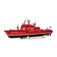
Montieren Sie den Regler direkt hinter dem Motor
und verbinden die Kabel zum Motor. Achten Sie
darauf, dass die Kabel nicht an der Motorglocke
schleifen können.
Die Akkus nden hinter dem Regler vor dem Rad-
kasten auf dem Montagebrett Platz und sollten mit
Klettschlaufen gesichert werden.
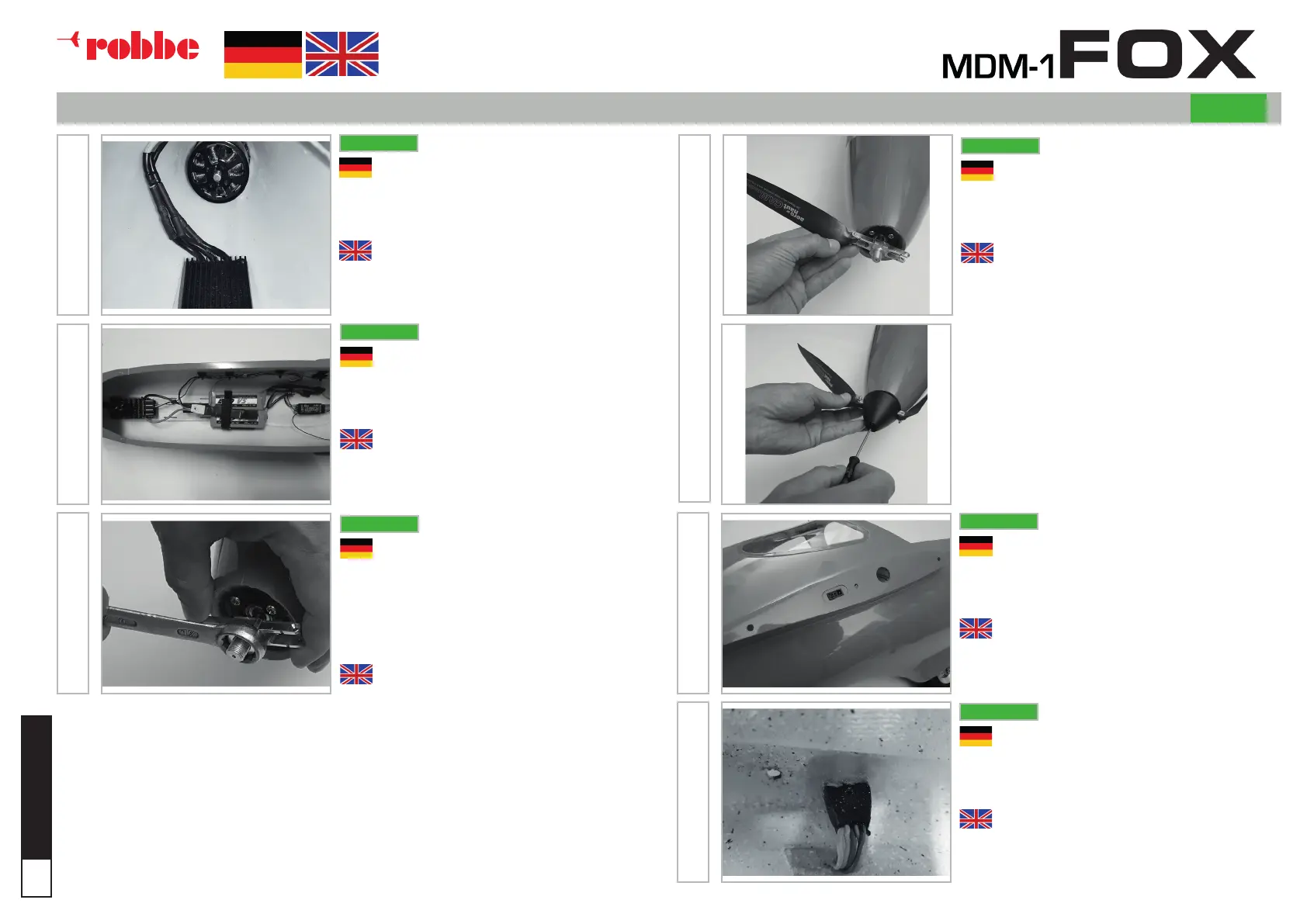
Montieren Sie das Luftschrauben Mittelteil auf der
Motorwelle. Achten Sie auf ein festes, aber gefühl-
volles Anziehen der Mutter. Es handelt sich hier um
ein Aluminium Gewinde!
Nun empfehlen wir bereits eine kurze Funktionskon-
trolle, um die Drehrichtung des Motors zu überprüfen.
Danach werden auch die Luftschraubenblätter und
die Spinnerkappe am Mittelteil montiert.
Für die elektrische Verbindung Rumpf/Fläche werden
die 6-poligen Mulltiplex Stecker verwendet, die
wahlweise lose belassen oder fest eingebaut werden
können.
Der feste Einbau erfordert zu Beginn etwas mehr
Aufwand, erleichtert aber den Zusammenbau der
MDM-1 FOX später auf dem Flugfeld enorm.
Mount the controller directly behind the motor and
connect the cables to the motor. Make sure that the
cables can not drag on the motor bell.
The batteries are located behind the controller in
front of the wheelhouse on the mounting board and
should be secured with Velcro straps.
Mount the propeller center section on the motor
shaft. Pay attention to a rm but sensitive tightening
of the nut. This is an aluminum thread!
Now we recommend a short function check to
check the direction of rotation of the motor.
Thereafter, the propeller blades and the spinner cap
are mounted on the middle section.
For the electrical connection fuselage / wing, the
6-pin Mulltiplex connectors are used, which can opti-
onally be left loose or permanently installed.
The xed installation requires a bit more effort at the
beginning, but facilitates the assembly of the MDM-1
FOX later on the aireld enormously.
PNP
PNP
PNP
PNP
PNP
PNP
MONTAGE DES RUMPFES / ASSEMBLY THE FUSELAGE
PNP
 Loading...