Electrical installer
26
4
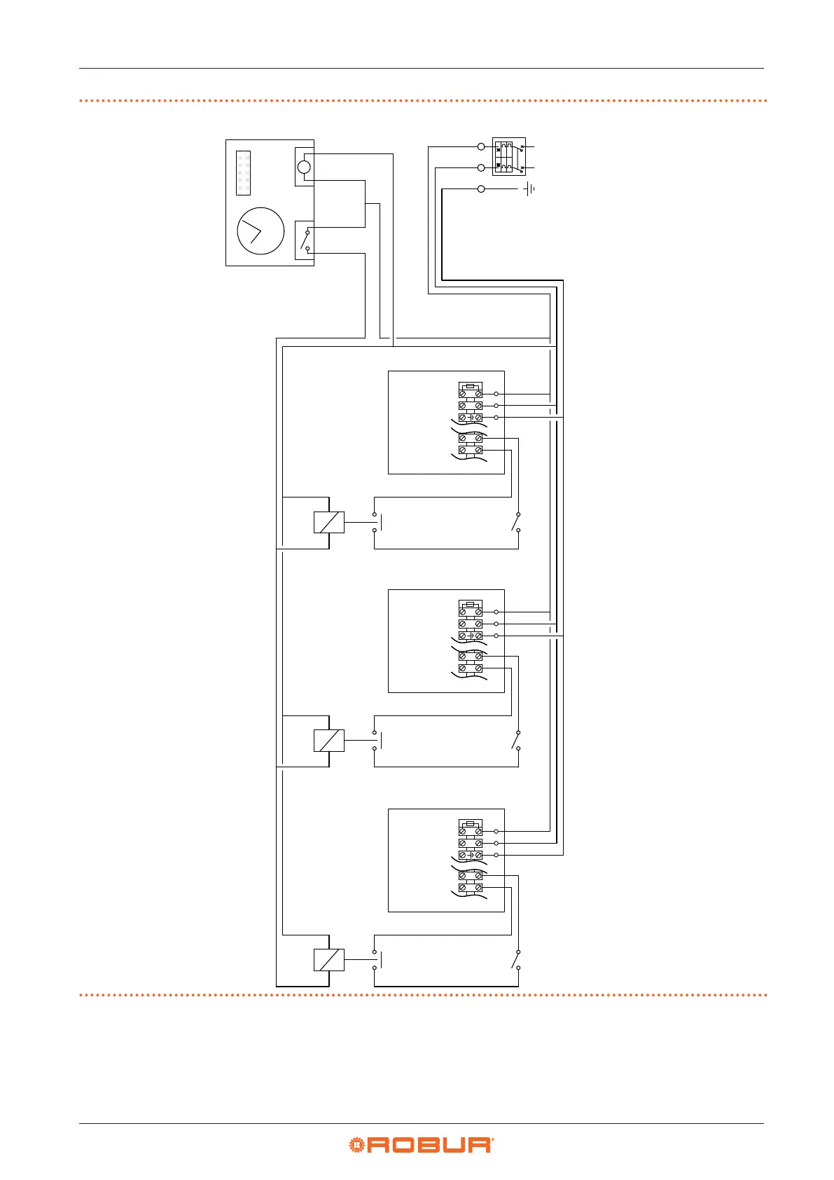
Figure4.5 Multiple appliances wiring diagram with one programmable timer and more room thermostats
A Gas unit heater
P Programmable timer
RL Relay
TA Room thermostat
L Phase
N Neutral
M
N L
230V~50Hz
A
TA
RL1
TA
RL2
TA
RL3
230V~50Hz
A
230V~50Hz
A
FUSE
N L
Z92
Z91
FUSE
N L
Z92
Z91
FUSE
N L
Z92
Z91
N L
Z92
Z91
N L
Z92
Z91
N L
Z92
Z91
4.4.3 Positioning the control system
Install the chosen thermostat/control system according to
the following guidelines:
▶
At about 1,5 m from the oor, protected against air
draughts, direct exposure to sun rays and direct heat
sources (lamps, hot air ow from the unit itself, etc.).
▶
If possible, do not place the control system on walls
bordering the outside, to avoid false temperature
readings and therefore aect system operation. If this
is not possible, shield the control system by placing a