4
Quantity
16 Base 1
17 Locking Caster 2
18 Caster 2
19 Leg Support 4
20 Vertical Support 2
21 Crossbar 1
22 Frame Assembly 1
23 Table Extension 1
24 Left Flip Stop 1
25 Right Flip Stop 1
26 Latch Arm 1
PARTS LIST
Material Mate
™
Assembly
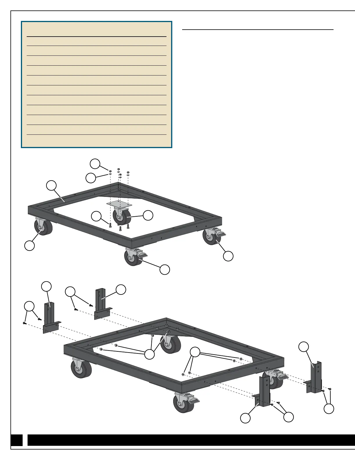
1. Attach the two Casters (18) and two Locking Casters (17)
to the Base (16) with 1/4" x 3/4" Hex Bolts (3), 1/4"
Washers (2) and 1/4" Lock Nuts (1). Fig. 1.
Make sure to install the casters in the orientation
shown — the Locking Casters (17) must be installed on
the same end of the base so they are side by side.
2. Attach the four Leg Supports (19) to the Base (16) with
1/4" x 5/8" Bolts (5) and 1/4" Flange Nuts (4). Fig. 2.
3. Slide the Vertical Supports (20) into the Leg Supports (19),
aligning the bottom set of holes in the Vertical Supports
with the holes in the Leg Supports, and secure with
1/4" x 1
1
⁄2" Bolts (6) and 1/4" Flange Nuts (4). Fig. 3.
You will need to adjust the height setting in a later step.
4. Position the Crossbar (21) between the Vertical Supports (20)
and attach with 1/4" x 1
1
⁄2" Bolts (6) and 1/4" Flange
Nuts (4). Fig. 3.
5. Attach a Safety Locking Pin (8) to the outside face of each
Vertical Support (20) with a 1/4" x 1/2" Bolt (7) threaded into
the integral nut in the support. Fig 3.
Fig. 1 - Base Assembly
Fig. 2 - Leg Support Assembly
1
2
16
18
3
17
17
5
19
5
19
5
5
19
19
18
4
4