Node Controller Overview
General Purpose Digital I/O
Node Controller Hardware User Manual 47
Rockwell Automation Publication MMI-UM013B-EN-P - April 2020
General Purpose Digital I/O
When using an NC-E or NC-12 node controller, digital inputs and outputs can be monitored
and controlled, respectively. These circuits can be wired directly to the digital I/O terminals
on the node controller for monitoring and control of local options or for any user-defined use.
These optional circuits are the responsibility of the user and require additional user-supplied
hardware including a power supply.
Functions such as E-stops, interlocks, and light stacks can be configured as part of transport
system operation. See the MagneMover LITE Configurator User Manual or the QuickStick
Configurator User Manual for information on digital I/O configuration and use.
The host controller can issue commands to set the value of the Digital Outputs, or read the
value of the Digital Inputs. See the Host Controller TCP/IP Communication Protocol User
Manual or the Host Controller EtherNet/IP Communication Protocol User Manual for details
on the use of the digital I/O.
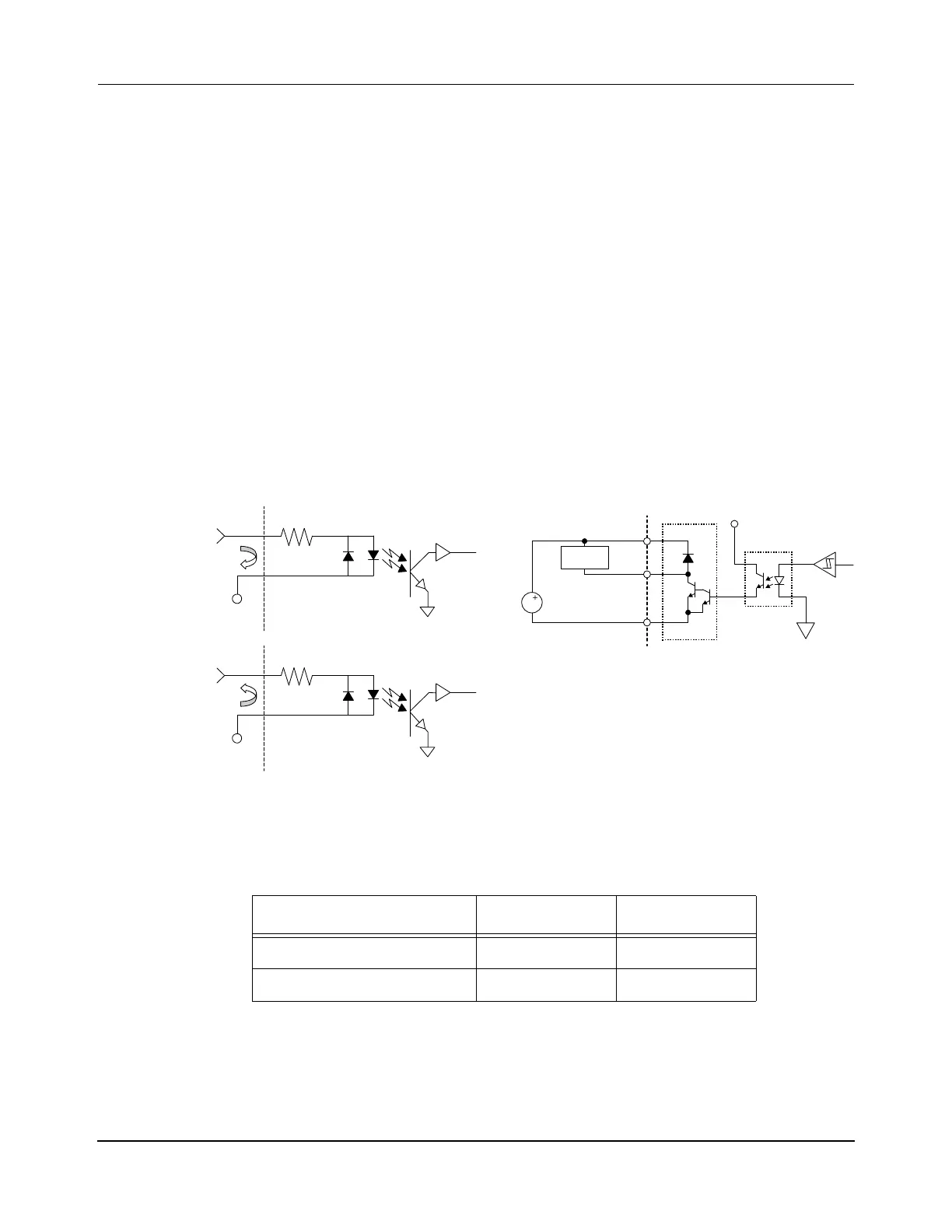
NOTE: An external power supply for the digital I/O circuits is required (see Figure 3-2).
Figure 3-2: Digital I/O Equivalent Circuits
NC-E Digital I/O Connection
The NC-E node controller provides four optically isolated digital input bits and four optically
isolated digital output bits. See Figure 4-12 for the location of these connections on the node
Table 3-2: Digital I/O Power Requirements
NC-E NC-12
Digital Inputs (+VDC) +5–24V DC +3–24V DC
Digital Outputs (DC) +5–35V DC +5–35V DC
Signal
COM
1.2K Ohm
1.2K Ohm
+VDC
Signal
+VDC
COM
RTN
RTN
DC
VDD
RTN
Load
V5V
PC 817
Darlington
Sink Driver
DOn
Digital Inputs Digital Outputs

 Loading...


